Table of Contents
Troubleshooting

Related Manuals for Loewe CENTROS 2102


Summary of Contents for Loewe CENTROS 2102
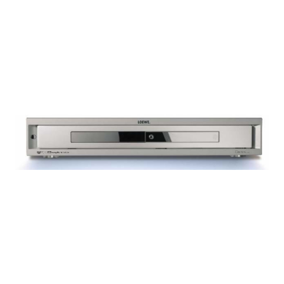
- Page 1 SERVICEANLEITUNG DVD Recorder Service Manual. Manuel de Service. Manuale di Servizio. 230- 90434.936 Instrucciones de servicio. Service-instructies. CENTROS 2102 Art.-Nr. 64502 CENTROS 2172 Art.-Nr. 64512 CENTROS 2102 HD / CENTROS 2172 HD...
- Page 2 CONTENTS SECTION 1 ..SUMMARY SECTION 2 ..CABINET & MAIN CHASSIS SECTION 3 ..ELECTRICAL SECTION 4 ..PARTS LIST...
-
Page 3: Table Of Contents
SECTION 1 SUMMARY CONTENTS NEW FUNCTIONS OF DVD-RECORDER ................1-2 PRODUCT SAFETY SERVICING GUIDELINES FOR VIDEO PRODUCTS ....1-3 SERVICING PRECAUTIONS ....................1-4 • General Servicing Precautions • Insulation Checking Prodedure • Electrostatically Sensitive Devices SERVICE INFORMATION FOR EEPROM IC SETTING .......... -
Page 4: New Functions Of Dvd-Recorder
NEW FUNCTIONS OF DVD-RECORDER • SUMMARY OF PRODUCT - RECORDING FUNCTION OF DVD-RW AND DVD-R SPECIFICATIONS • DVD-RW: VIDEO MODE AND VR MODE RECORD AVAILABLE • DVD-R :VIDEO MODE RECORD AVAILABLE - DIGITAL DUBBING FUNCTION OF DV CAMCORDER BY USING DV TERMINAL (IEEE1394) •... -
Page 5: Product Safety Servicing Guidelines For Video Products
When servicing this product, under no circumstances should the original design be modified or altered without permission from LOEWE Electronics Corporation. All components should be replaced only with types identical to those in the original circuit and their physical location, wiring and lead dress must conform to original layout upon completion of repairs. -
Page 6: Servicing Precautions
SERVICING PRECAUTIONS CAUTION : Before servicing the DVD Recorder covered by Electrostatically Sensitive (ES) Devices this service data and its supplements and addends, read and Some semiconductor (solid state) devices can be damaged follow the SAFETY PRECAUTIONS. NOTE : if unforeseen easily by static electricity. -
Page 7: Service Information For Eeprom Ic Setting
SERVICE INFORMATION FOR EEPROM IC SETTING OPTION MICOM START CONFIRMATION MODE EEPROM ID CHECK Press the "END" key on CENTROS 2102 HD NAME HEX BINARY 2 BYTE(B3,248,249) the Remote controller and OPT1 11111000 the "SCAN - " key one the... -
Page 8: Specifications
SPECIFICATIONS • GENERAL Power requirements AC 200-240V, 50/60 Hz Power consumption Dimensions (approx.) 430 X 92 X 382.5 mm (16.9 x 3.6 x 15 inches) (w x h x d) Mass (approx.) 6.4 kg (14.1 lbs) Operating temperature 5˚C to 35˚C (41˚F to 95˚F) Operating humidity 5 % to 90 % Television system... - Page 9 SECTION 2 CABINET & MAIN CHASSIS CONTENTS EXPLODED VIEWS ........................2-2 1. Cabinet and Main Frame Section ..................2-2 2. Deck Mechanism Section(MTK) ....................2-3...
- Page 10 EXPLODED VIEWS 1. Cabinet and Main Frame Section NOTES) Warning NOTES) Parts that are shaded are critical NOTES) With respect to risk of fire or NOTES) electricial shock.
- Page 11 2. DECK MECHANISM SECTION(MTK)
- Page 12 SECTION 3 ELECTRICAL CONTENTS VDR PART ELECTRICAL TROUBLESHOOTING GUIDE ....................3-2 BLOCK DIAGRAMS ............................3-18 1. POWER(SMPS) BLOCK DIAGRAM......................3-18 2. VIDEO BLOCK DIAGRAM_PAL ......................3-20 3. AUDIO BLOCK DIAGRAM PAL .......................3-22 CIRCUIT DIAGRAMS............................3-24 1. POWER CIRCUIT DIAGRAM ........................3-24 2. I/O MICOM CIRCUIT DIAGRAM ......................3-26 3.
-
Page 13: Vdr Part
VDR PART ELECTRICAL TROUBLESHOOTING GUIDE No 5.3VA Is the F101 Replace the F101 Is the D126 Replace the D126 Normal? (Use the same Fuse) Normal? Is the BD101 Is the D127 Replace the BD101 Replace the D127 Normal? Normal? Power Line of Main Is the R101 Normal? Replace the R101 PCB is short... - Page 14 No 5VD No 5VT Is the Vcc(3.3V) sup- Check or Replace Is the Vcc(3.3V) sup- Check or Replace plied to Q162 Emittor? the D123 plied to Q164 Emittor? the D123 Is the Q162 Base Check the TIMER “H” Check the PWR CTL Is the Q164 Base ‘H’? ‘H’? signal from µ-com...
- Page 15 No 12VL No 12VT(12VG) Is the Vcc(13.5V) sup- Check or Replace Is the Vcc(13.5V) sup- Check or Replace plied to IC152 pin 1? the D127 plied to IC151 pin 1? the D127 Is the IC152 pin4 Check the PWR CTL Is the IC151 pin4 Check the GREEN ‘H’?
- Page 16 No 3.3V(HDMI) No 2.5V Is the Vcc(3.8V) sup- Check or Replace Is the Vcc(3.8V) sup- Check or Replace plied to IC155 pin 1? the D124, D125 plied to IC154 pin 1? the D124, D125 Is the IC155 pin4 Check the PWR CTL Is the IC154 pin4 Check the PWR CTL ‘H’?
- Page 17 SYSTEM Section LOEWE logo not displayed at POWER ON Check IC504 power and other IC504 12 JIGH? (RESET) circuits X501 : Clock oscillated ? Replace X501 ( 27 MHz ) IC502-24 : Check IC504 power and other Check signal(D_CS#) circuits...
- Page 18 When playing DISC, no audio output IC701 - 58: HIGH ? Check IC701 power and ( LOW: AUDIO MUTE ) other circuits Check IC805 power and IC805 – 15, 18 other circuits Check audio output IC805 - 10 : HIGH ? Check IC501 204 pin (DAC RESET status) IC802 - 7, 8 :...
- Page 19 No TUNER audio output Audio output even when < When playing DISC, no audio output. > Check playing DISC Check IC810,809 (AUDIO SWITCH) power and IC809, 810 Switching operation Check audio signal output Pin 2,4 High/Low =>Pin 7 output : SW_A_OUT_L/R IC808, 809, 810 Check IC810,809 signal flow...
- Page 20 IC812 - 2 : Check SIF Check C920, TUNER signal flow signal input\ When changing a channel, IC701 - Check IC701 power and 8 :HIGH after RESET signal? other circuits No TUNER VIDEO signal input Check C724 with IC703 circuit Check TUNER power and other circuits...
- Page 21 No external input 1 audio Audio output < When playing DISC, no audi o output > Check even when playing DISC IC810,809 (AUDIO SWITCH) IC809, 810 Check power and switching operation Check audio signal output Pin 2,4 High/Low =>Pin 7 output : SW_A_OUT_L/R IC809, 810 Check IC810,809 signal flow and...
- Page 22 No external input 2 audio Audio output < No audio output when playing DISC > Check even when playing DISC IC810,809 (AUDIO SWITCH) IC809 8, 10 Check power and switching operation Check audio signal output Pin 2,4 High/Low =>Pin 7 output : SW_A_OUT_L/R IC7809, 810 Check IC810,809 signal flow...
- Page 23 No external input 3 audio Audio < No audio output when playing DISC > Check output even when playing DISC IC810,809 (AUDIO SWITCH) IC809, 810 Check power and switching operation Check audio signal output Pin 2,4 High =>Pin 7 output : A1_L/R Pin 2,4 High/Low =>Pin 7 output : TU_L/R IC809, 810 Check JK803, 804...
- Page 24 No external input 4 audio Audio < No audio output when playing DISC > Check output even when playing DISC IC810,809 (AUDIO SWITCH) IC809,810 Check power and switching operation Check audio signal output Pin 2,4 Low =>Pin 7 output : A2_L/R Pin 2,4 High/Low =>Pin 7 output : TU_L/R IC809 810 Front Jack JK803, Jk804...
- Page 25 No RGB / Component video signal when playing DISC SW801 Q High? Check other circuits around IC701 91 : HIGH ? Q805 Collector High? IC701 Check IC701 60 : High input IC806 ñ 16,18,20 IC807 – 18, 21, 27 IC807 power and other circuits Pr,Pb,Y output? R,G,B output? Signal after checking R896, 831,...
- Page 26 No COMPOSIT / S-VIDEO signal when playing DISC No COMPOSIT signal? S-VIDEO: No Y signal? S-VIDEO : No C signal? IC808 – 29,30 Check R935 Check R936 Check output IC807 - 6 IC807 - 8 IC807 - 4 Check output Check output Check output Check R871,C834...
- Page 27 No TV , external input video signal No video signal of external input 1/2 When connecting Tuner, No video signal of external input 3/4 ( Rear Comosite input ) no TV video signal ( Front S-VIEDO / Comosite input ) Check IC808 - 1,3(input) and 31 IC501 246, 248 Check Tuner power and other...
- Page 28 No DV( IEEE 1394 ) input (video/audio) signal Check DV_JACK and CABLE connection IC507 - 27, 28, 29, 30 Check signal input IC507 -37 : HIGH? Check L509 Voltage ( /RST_PHY ) Check X503 Clock Check IC507 - 2 Clock? 24.576 MHz BIO_PHY_CLK IC3048 =>...
-
Page 30: Block Diagrams
BLOCK DIAGRAMS 1. POWER(SMPS) BLOCK DIAGRAM RECTIFIER(VF+) RECTIFIER(-28V) -26VA RECTIFIER(33VA) RECTIFIER(15V) REG(12V) 12VG REG(12V) 12VL RECTIFIER(15V) REG(12V) 3.3V REG(3.3V) 3.3VL RECTIFIER(4.3V) REG(3.3V) 3.3V(HDMI) 2.5V REG(2.5V) 2.5 VL 5V_M REG(5V) 5V_Loader RECTIFIER(5.3VA) 5.3VA FEED B. PWR CTL AC100~240V GREEN "H" TIMER "H" NOTES) Warning NOTES) - Page 31 2. VIDEO BLOCK DIAGRAM_PAL TUNER_VIDEO TUNER RF SIGNAL TUNER TU_VIDEO MM1510 SW_V_OUT SDA5650 SDA5650 VPS/PDC VPS/PDC R_SCART_IN G_SCART_IN B_SCART_IN 24.576MHz RGB_IN MM1232 EU2_V_OUT TPA+/- MM1443 TSB41AB1 TSB41AB1 TPB+/- EU2_V_IN AV S/W 4in/3out 1394 PHY 1394 PHY C+_DET_H Canal Plus V1: Tu/E1/E2 Front Dis play SCART_H Front Dis play...
-
Page 32: Audio Block Diagram Pal
3. AUDIO BLOCK DIAGRAM PAL SPDIF Front RCA IN(V,A.L/R) COAXIAL/OPTICAL Front RCA IN(V,A.L/R) COAXIAL/OPTICAL TUNER RF SIGNAL TUNER 18.432MHz SIF IN MM1232 MSP34x7 TU_A_L_OUT Sound S/W_V_O TUN-L TU_A_R_OUT Processor EU2_A_IN_L S/W_A_L TUN-R E2-L EU2_A_IN_R S/W_A_R E2-R EU2_A_OUT_L LOUT2 EU2_A_OUT_R 27MHz 32.768Khz ROUT2 MM1443... -
Page 33: Circuit Diagrams
CIRCUIT DIAGRAMS IMPORTANT SAFETY NOTICE CUIT. SPECIAL COMPONENTS ARE SHADED ON THE NOTE : SCHEMATIC FOR EASY IDENTIFICATION. 1. Shaded( ) parts are critical for safety. Replace only WHEN SERVICING THIS CHASSIS, UNDER NO CIR- THIS CIRCUIT DIAGRAM MAY OCCASIONALLY DIF- with specified part number. -
Page 34: I/O Micom Circuit Diagram
2. I/O MICOM CIRCUIT DIAGRAM 3-26 3-27... -
Page 35: Tuner/Mpx/Adc/Dac/Jack Circuit Diagram
3. TUNER/MPX/ADC/DAC/JACK CIRCUIT DIAGRAM 3-28 3-29... -
Page 36: Hdmi Circuit Diagram
4. HDMI CIRCUIT DIAGRAM 3-30 3-31... -
Page 37: Mpeg Circuit Diagram
5. MPEG CIRCUIT DIAGRAM 3-32 3-33... -
Page 38: Timer/Key Circuit Diagram
6. TIMER/KEY CIRCUIT DIAGRAM 3-34 3-35... -
Page 39: Front Av Jack Circuit Diagram
7. FRONT AV JACK CIRCUIT DIAGRAM 3-36 3-37... -
Page 40: Front Av Jack_Dv+Super Circuit Diagram
8. FRONT AV JACK_DV+SUPER CIRCUIT DIAGRAM 3-38 3-39... -
Page 41: Circuit Voltage Chart
• CIRCUIT VOLTAGE CHART MODE MODE MODE MODE MODE MODE MODE PIN NO. PIN NO. PIN NO. PIN NO. PIN NO. PIN NO. PIN NO. IC501 5.16 5.16 5.16 5.16 5.16 5.16 5.19 5.19 4.25 4.24 4.24 5.19 5.19 5.19 5.08 5.06 5.06... - Page 42 MODE MODE MODE MODE MODE MODE PIN NO. PIN NO. PIN NO. PIN NO. PIN NO. PIN NO. IC801 5.05 5.05 5.05 5.17 5.16 5.16 2.18 2.18 2.18 1.72 1.71 1.74 5.05 5.05 5.05 4.77 4.94 4.82 2.34 2.34 2.34 5.21 5.21 5.21...
-
Page 43: Printed Circuit Diagrams
PRINTED CIRCUIT DIAGRAMS 1. MAIN P.C.BOARD (TOP SIDE) 3-44 3-45... -
Page 44: Main P.c.board(Bottom Side)
2. MAIN P.C.BOARD (BOTTOM SIDE) 3-46 3-47... -
Page 45: Jack P.c.board
3. JACK P.C.BOARD (TOP SIDE) (BOTTOM SIDE) 4. FRONT P.C.BOARD (TOP SIDE) (BOTTOM SIDE) 3-48 3-49... -
Page 46: Key Timer P.c.board
5. KEY TIMER P.C.BOARD 6. POWER P.C.BOARD (TOP SIDE) NOTES) Warning NOTES) Parts that are shaded are critical NOTES) With respect to risk of fire or NOTES) electricial shock. (TOP SIDE) 3-50 3-51... -
Page 48: Mtk Loader Part
MTK LOADER PART ELECTRICAL TROUBLESHOOTING GUIDE Reset or Power Check. Check it after connecting the power cable only for NO Reset or Power ON. •Check the power(5V,12V)short. Are the pin 41, 44 of CN201 •Check the PC power cable. +12V, +5V respectively after the power •Repair the PC power supply. - Page 49 System Check Load tray without inserting disc. Does tray operate normally? Go to “Tray operating is abnormal” Does pick-up move to inside? Go to “Sled operating is abnormal” Go to “Focus Actuator operating is Does pick-up lens move abnormal” up/down? Does laser turn on? Go to “Laser operating is abnormal”...
- Page 50 Tray operating is abnormal Tray open doesn ’t work. • Check the connection of IC302 pin 46. Is there tray • Replace the IC201. control signal input? • Check the communication line between (IC201 pin17) IC302 and IC201. Is there tray When CN303 is open, drive voltage output? Is there tray drive signal...
- Page 51 Sled operating is abnormal Is there sled control signal output? Replace the IC201 (IC201 pin 12, 15) Is there • Check the connection of IC302 pin 29, 30. sled drive signal input? • Replace the IC302. (IC302 pin29, 30) Is there Is CTRL1 sled drive voltage output? signal “H”?
- Page 52 Spindle operating is abnormal Is there Is there spindle control DSP spindle control signal input? output(IC201 pin 14)? (IC302 pin 26) • Check the R260 Replace the IC201. Is there Is there spindle drive voltage output? FG signal input? (IC302 pin 11, 13, 16) (IC201 pin 34 Replace the Spindle Motor •Check the connection of IC302 pin 43.
- Page 53 Focus Servo is unstable Is FE signal output normal in Focusing Replace the IC301. Up/Down? (IC301 pin 121) Is FDRV signal output normal in Focusing • Check the R256. Up/Down? • Replace the IC201. (IC201 pin 10) Go to “Focus Actuator operating is abnormal”...
- Page 54 Track Servo is unstable Is pick-up Is TE signal (A, B, C, D, E, F, G, H) output normal in focusing output normal? ON and tracking OFF? (CN308 pin 19, 20,28, (IC301 pin 119) 29, 27, 21, 30, 18) Replace the IC301. •Check the pick-up FFC.
- Page 55 Recognition Fail Case 1: CD-ROM Fail Check pick-up CD read power Go to “LD CHECK”. is 0.8 ~ 1.2mW? Does focus servo Go to “Focus Servo is unstable”. operate normally? Check pick-up RF signal IC301(Pin20) •Check the pick-up FFC and CN308. RF(TP42) is •Replace the pick-up unit.
- Page 56 Recognition Fail Case 2:DVD Fail Check pick-up DVD read power Go to “LD CHECK”. was 1.0~1.4mW? Is IC301 pin 79(LDEN-DVD)level Replace the IC301. was about 3.3V? Is there RF signal at CN308 Replace the pick-up. pin 25, 26. Is there RF1, RF2 signal Replace the IC301 at IC301 pin 30, 31.
- Page 57 LD CHECK (Laser operating is abnormal) Check reference voltage. OFF level VRDC level &FPD VWDC1 level &FPD VWDC2 level &FPD VRDC VWDC2 VWDC1 3-61...
- Page 58 CD/DVD ? Check the input of LDEN-CD. Check the input of LDEN-DVD. (pin 49 of CN308 : ‘H ’) (pin 50 of CN308 : ‘H ’) Check the input of VRDC. (pin 37 of CN308) Check the input of FPD. (pin 13 of CN308) 3-62...
- Page 59 Check the input of LDEN-DVD. Check the input of LDEN-DVD. (pin 50 of CN308 : ‘H’) (pin 50 of CN308 : ‘H’) Check the input of VWDC1. Check the input of VWDC2. (pin 25 of CN308 (pin 34 of CN308) Check the input of recording pulse.
- Page 60 In case of writing fail. Normal Case Check the media Check disc label. DVD ±R/RW? Does the disc Remove the dust,fingerprint and have any dust,scratch, if the disc has long width scratch, fingerprint …? change it. Insert disc to the DVR set Check disc information on writing tool.
- Page 61 Writing Part Check Load tray with DVD ±R/RW disc. Recording with DVR set. Does writing finish without any error? Is the record video Eject tray. read normally? Go to “LD CHECK”. Is the re-written file read normally? Check and replace IC107,IC202. 3-65...
-
Page 62: Block Diagrams & Description
BLOCK DIAGRAMS 1. SERVO SYSTEM BLOCK DIAGRAM Sled, spindle & tray Pick-up Head 3-66... -
Page 63: Mt1816 Block Diagram
2. MT1816 BLOCK DIAGRAM R/W LDON R/W FPDSH WOBZCK WOBDATA RF+/- RFOP,RFON 3-67... -
Page 64: Mt1818 Block Diagram
3. MT1818 BLOCK DIAGRAM R/W LDON, S & H WOBZCK, WOBDATA LO,RO 3-68... -
Page 66: Circuit Diagrams
CIRCUIT DIAGRAMS 1. RF CIRCUIT DIAGRAM 3-69 3-70... -
Page 67: Dsp Circuit Diagram
2. DSP CIRCUIT DIAGRAM 3-71 3-72... -
Page 68: Printed Circuit Diagrams
PRINTED CIRCUIT DIAGRAMS 1. MAIN P.C.BOARD ( TOP VIEW ) ( BOTTOM VIEW ) 3-73 3-74...
Need help?
Do you have a question about the CENTROS 2102 and is the answer not in the manual?
Questions and answers