Table of Contents
Advertisement
Quick Links
Advertisement
Table of Contents

Related Manuals for Measurement Computing USB-DIO24/37

Summary of Contents for Measurement Computing USB-DIO24/37
- Page 2 USB-DIO24/37 Digital Input/Output User’s Guide Document Revision 1, July, 2005 © Copyright 2005, Measurement Computing Corporation...
- Page 3 Measurement Computing. Thank you for choosing a Measurement Computing product—and congratulations! You own the finest, and you can now enjoy the protection of the most comprehensive warranties and unmatched phone tech support. It’s the embodiment of our...
- Page 4 Information furnished by Measurement Computing Corporation is believed to be accurate and reliable. However, no responsibility is assumed by Measurement Computing Corporation neither for its use; nor for any infringements of patents or other rights of third parties, which may result from its use. No license is granted by implication or otherwise under any patent or copyrights of Measurement Computing Corporation.
-
Page 5: Table Of Contents
Introducing the USB-DIO24/37......................1-1 Overview: USB-DIO24/37 features........................ 1-1 USB-DIO24/37 block diagram ........................1-1 Software features ............................1-2 Connecting a USB-DIO24/37 to your computer is easy................. 1-2 Chapter 2 Installing the USB-DIO24/37......................2-1 What comes with your USB-DIO24/37 shipment?..................2-1 Hardware ..................................2-1 Software.................................. -
Page 6: About This User's Guide
What you will learn from this user's guide This user's guide explains how to install, configure and use the USB-DIO24/37 digital I/O board. This user's guide also refers you to related documents available on our web site and to technical support resources. -
Page 7: Introducing The Usb-Dio24/37
Introducing the USB-DIO24/37 Overview: USB-DIO24/37 features This manual explains how to install, configure and use the USB-DIO24/37 digital I/O board. You can use this board in a variety of digital applications to control logic devices such as switches, gauges, relays, pumps, and sensors. -
Page 8: Software Features
Microsoft HID because it is a standard, and its performance delivers full control and maximizes data transfer rates for your USB-DIO24/37. No third-party device driver is required. The USB-DIO24/37 is plug-and-play. There are no jumpers to position, DIP switches to set, or interrupts to configure. -
Page 9: Installing The Usb-Dio24/37
Hardware USB-DIO24/37 USB cable (2 meter length) Software The Measurement Computing Data Acquisition Software CD contains the following software: InstaCal installation, calibration, and test utility TracerDAQ suite of virtual instruments SoftWIRE for VS .NET SoftWIRE MCC DAQ Components for .NET... -
Page 10: Optional Components
Fax: 508-946-9500 to the attention of Tech Support Email: techsupport@measurementcomputing.com Installing the software Refer to the Quick Start Guide for instructions on installing the software on the Measurement Computing Data Acquisition Software CD. This booklet is available in PDF at www.mccdaq.com/PDFmanuals/DAQ-Software-Quick-Start.pdf. -
Page 11: Installing The Usb-Dio24/37
Connecting the USB-DIO24/37 to your system To connect the USB-DIO24/37 to your system, connect the USB cable to a USB port on your computer or to an external USB hub that is connected to your computer. The USB cable provides communication to the USB-DIO24/37. -
Page 12: Pin Out - Main I/O Connector
USB-DIO24/37 User's Guide Installing the USB-DIO24/37 Pin out – main I/O connector Port C Bit 7 22 Port B Bit 7 Port C Bit 6 23 Port B Bit 6 Port C Bit 5 24 Port B Bit 5 Port C Bit 4 25... -
Page 13: Field Wiring, Signal Termination And Conditioning
USB-DIO24/37 User's Guide Installing the USB-DIO24/37 Field wiring, signal termination and conditioning You can connect the USB-DIO24/37 to the following accessory boards using the C37FF-x or C37FFS-x cable. SCB-37 – 37-conductor, shielded signal connection/screw terminal box. Details on this product are available on our web site at www.mccdaq.com/cbicatalog/cbiproduct.asp?dept_id=196&pf_id=1166. -
Page 14: Functional Details
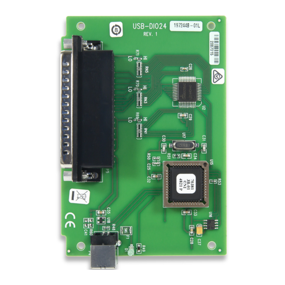
Chapter 3 Functional Details Components The USB-DIO24/37 has the following components, as shown in Figure 3-1. 37-pin I/O connector USB connector Connector 37-pin I/O connector Figure 3-1. USB-DIO24/37 components 37-pin I/O connector The 37-pin connector provides 24 digital I/O, one counter, six ground, and two 5V power connections. -
Page 15: Usb Connector
The USB connector provides +5 V power and communication. The voltage supplied through the USB connector is system-dependent, and may be less than 5 V. No external power supply is required. The LED indicates the communication status of the USB-DIO24/37. It uses up to 5 mA of current and cannot be disabled. Ta ble 3-2 explains the function of the USB-DIO24/37 LED. -
Page 16: Specifications
Chapter 4 Specifications Typical for 25 °C unless otherwise specified. Specifications in italic text are guaranteed by design. Digital input/output Table 4-1. Digital I/O specifications Digital type 82C55 Number of I/O 24 (Port A Bit 0 through Port C Bit7) Configuration 2 banks of 8 and 2 banks of 4 or 3 banks of 8... -
Page 17: Power
460 mA max Connected to Bus-Powered Hub 60 mA max This is the total current requirement for the USB-DIO24/37 which includes up to 5 mA for Note 2: the status LED. Self-powered refers to USB hubs and hosts with a power supply. Bus-powered refers to Note 3: USB hubs and hosts without their own power supply. -
Page 18: Main Connector And Pin Out
USB-DIO24/37 User's Guide Specifications Main connector and pin out Table 4-8. Connector specifications Connector type 37-Pin D-type Compatible cables C37FF-x unshielded ribbon cable. x = length in feet. C37FFS-x cable shielded round cable. x = length in feet. Compatible accessory products (with the... - Page 19 EC Declaration of Conformity We, Measurement Computing Corporation, declare under sole responsibility that the product USB-DIO24/37 USB-based 24-bit digital IO board Part Number Description to which this declaration relates, meets the essential requirements, is in conformity with, and CE marking...
- Page 20 Measurement Computing Corporation 16 Commerce Boulevard, Middleboro, Massachusetts 02346 (508) 946-5100 Fax: (508) 946-9500 E-mail: info@mccdaq.com www.mccdaq.com...
Need help?
Do you have a question about the USB-DIO24/37 and is the answer not in the manual?
Questions and answers