Table of Contents
Advertisement
Quick Links
Model Numbers:
Certified to:
This appliance may be installed in an aftermarket, permanently located, manufactured home (USA
only) or mobile home, where not prohibited by local codes.
This appliance is only for use with the type of gas indicated on the rating plate. This appliance is not
convertible for use with other gases, unless a certified kit is used.
⚠
WARNING:
FIRE OR EXPLOSION HAZARD
Failure to follow safety warnings exactly could result in serious injury, death, or property damage.
-Do not store or use gasoline or other flammable vapors and liquids in the vicinity of this or any other
appliance.
-WHAT TO DO IF YOU SMELL GAS
• Do not try to light any appliance.
• Do not touch any electrical switch; do not use any phone in your building.
• Leave the building immediately.
• Immediately call your gas supplier from a neighbor's phone. Follow the gas supplier's
instructions.
• If you cannot reach your gas supplier, call the fire department
-Installation and service must be performed by a qualified installer, service agency or the gas
supplier.
Installation Instructions
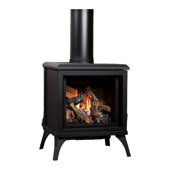
Model Number FDV200S
Free Standing Direct Vent Gas Stove
FDV200SN, FDV200SNE, FDV200SNE2, FDV200SLP, FDV200SLPE, FDV200SLPE2
ANSI Z21.88-2017 • CSA 2.33-2017, CSA 2.17-2017
VENTED GAS FIREPLACE HEATER
INSTALLER: Leave this manual with the
appliance.
CONSUMER: Retain this manual for future
reference.
For Propane Horizontal installations
the venting must be an additional one
foot above the minimum vertical rise
off the flue before going horizontal.
VENTED GAS FIREPLACE HEATER:
NOT FOR USE WITH SOLID FUEL.
A Division of R-Co. Inc.
2340 Logan Ave.
Winnipeg, Manitoba Canada
R2R 2V3 Ph.: (204) 632-1962
Printed in Canada January 5, 2022
Part# 200S-MAN17
TITAN
Advertisement
Table of Contents

Related Manuals for Kingsman Fireplaces FDV200SN


Summary of Contents for Kingsman Fireplaces FDV200SN
- Page 1 Model Number FDV200S Free Standing Direct Vent Gas Stove TITAN Model Numbers: FDV200SN, FDV200SNE, FDV200SNE2, FDV200SLP, FDV200SLPE, FDV200SLPE2 ANSI Z21.88-2017 • CSA 2.33-2017, CSA 2.17-2017 Certified to: VENTED GAS FIREPLACE HEATER This appliance may be installed in an aftermarket, permanently located, manufactured home (USA only) or mobile home, where not prohibited by local codes.
-
Page 2: Table Of Contents
FDV200S Table of Contents Table of Contents………………………………………………………............Safety Screen Attachment / Removal......................Pre-installation Questions and Answers / Operating Instructions............... Annual Inspection List for Determining Safe Operation of a Direct Vent Gas Fireplace......Warnings, Installations, and Operations……………………………………………………......Installation Requirements for the Commonwealth of Massachusetts............Carbon Monoxide (CO) Detector........................ - Page 3 PARTS LIST FDV200S Parts List............................ 48-49 WARRANTY Glass Safety / Termination Cap Safety....................... Limited Lifetime Warranty...........................
-
Page 4: Safety Screen Attachment / Removal
FDV200S Safety Screen Attachment / Removal Top Hook INSTALLATION: 1. Insert top of Screen Frame into bottom of stove top. 2. Engage Top Hooks into Top Slots. 3. Engage Bottom Hooks into Top Hook Bottom Slots. Safety Screen Frame Bottom Hook Assembly Bottom Hook Top Slot... -
Page 5: Pre-Installation Questions And Answers / Operating Instructions
Pre-installation Questions and Answers About curing of the paint Your stove or fireplace has been painted with the highest quality silicone stove paint. This paint dries quickly in 15-20 minutes when first applied at the factory. However, due to the high temperature silicone components, the paint will cure when heat is applied to the appliance as it is first used. -
Page 6: Annual Inspection List For Determining Safe Operation Of A Direct Vent Gas Fireplace
Annual Inspection List for Determining Safe Operation of a Direct Vent Gas Fireplace Refer to this checklist for proper maintenance, safe use, and operation. See each section for more specific information. 1. Inspect and operate all pressure relief mechanisms (i.e., relief dampers, spring loaded door latches) installed on your appliance to verify relief mechanisms are free from obstruction to operate. -
Page 7: Warnings, Installations, And Operations
Warnings, Installations and Operations - Installation Regulations This gas appliance must be installed by a qualified installer in accordance with local building codes, or in the absence of local codes, with the current CAN/CSA-B149.1 or .2 Installation Code (in Canada) or the current National Fuel Gas Code Z223.1- NFPA 54 when installed in the United States. -
Page 8: Installation Requirements For The Commonwealth Of Massachusetts
Installation Requirements for the Commonwealth of Massachusetts In the Commonwealth of Massachusetts, the installer or service agent shall be a plumber or gas fitter licensed by the Commonwealth. When installed in the Commonwealth of Massachusetts or where applicable codes; the unit shall be installed with a CO detector per the requirements listed below. -
Page 9: Mobile Home/Manufactured Housing Installation
Mobile Home/Manufactured Housing Installation This Direct Vent System Appliance must be installed in accordance with the manufacturer’s installation instructions and the Manufactured Home Construction and Safety Standard Title 24 CFR, Part 3280, or the current Standard for Fire Safety Criteria for Manufactured Home Installations, Sites, and Communities ANSI/NFPA 501A, and with CAN/CSA Z240 MH Mobile Home Standard in Canada. -
Page 10: Fireplace Dimensions / Locating Your Appliance
FDV200S Dimensions VENTING IS 4” / 7” Gas Inlet is located at the back of the unit. FDV200S Locating Your Appliance 3” 3” 6” 3” THE FOLLOWING MINIMUM DISTANCES TO 4” 2-1/2” COMBUSTIBLES MUST BE OBSERVED TO ENSURE SAFE OPERATION OF YOUR STOVE. Side of Unit 6”... -
Page 11: Component Locations
FDV200S Component Locations PROFLAME 1 MILLIVOLT Piezo Igniter Valve Remote Remote Receiver / Valve Receiver Battery Backup Proflame1 Module Fan Speed Control Fan Speed Control TOP VIEW TOP VIEW Proflame1 Module Remote Receiver Remote Receiver / Valve Piezo Igniter Fan Speed Control Valve Battery Backup Fan Speed Control... -
Page 12: Component Cover
FDV200S Component Cover The Component Cover is located directly below the Control Panel. ⚠ WARNING: Wait until unit is COMPLETELY cool before attempting to install or remove components. Control Component Cover Panel Component Cover To Remove Component Cover: Rear Tab Rear Tab Screw Remove the [2] DT screws at the front of the Component Cover. -
Page 13: Optional Fan Kit Installation
FDV200S Optional Fan Installation (Part # F45FK) -
Page 14: Split Receptacle- Switch Control Outside Of Fireplace
Fan Speed Control Outside of Fireplace If you plan to locate the variable speed control switch for the fan outside of the fireplace and you require a constant source of AC power inside the unit for another accessory such as lights or an IPI valve system, follow one of the procedures below. -
Page 15: F200Rl Brick Liner Installation
FDV200RL Brick Liner Installation Installation of Brick Panel Kit: 1. Remove glass door as shown in door removal diagram. 2. Place Back Brick Panel up to rear of firebox, leaving bottom of panel slightly forward for support. 3. Remove left and right Brick Clips using a 1/4” nut driver. Do not discard Brick Clips. 4. -
Page 16: Logc200 Log Installation
LOGC200 Installation Instructions Locating Tabs ⚠ WARNING: Failure to position the parts in accordance with these diagrams or failure to use only parts specifically approved with this appliance may result in property damage or personal injury. Step 1: Step 2: Log 1 is The hole in the installed onto... -
Page 17: Door And Glass Information
Door and Glass Information FDV200S Screw Screw Glass Front Door Assembly Safety Screen Frame Assembly... -
Page 18: Gas Line Installation
Massachusetts. This is in reference to the state Shutoff valves installed in tubing systems of Massachusetts state code CMR238. shall be rigidly and securely supported independently of the tubing. Gas Specifications MODELS FDV200SN FDV200SNE FDV200SLP FDV200SLPE FDV200SNE2 FDV200SLPE2 Fuel Natural... -
Page 19: Burner System Maintenance
Conversion #30 (977.167) (0.907.202) (FDV200SLP) Open -Millivolt- NG Conversion 1001-P165SI 1001-P201SI 200DV-CKNG 1000-253 closed 3/8” -Millivolt- #51 (977.165) (0.907.201) (FDV200SN) Propane 1001-P168SI 1002-P014SI 200DV-CKLPI 1/16” 1000-253 closed Full Conversion #35 (977.168) (0.907.014) (FDV200SLPE) Open -Proflame 1 - NG Conversion 1001-P166SI... -
Page 20: Conversion Kit Instructions -Part A
Conversion Kit Instructions -Part A Caution: The gas supply shall be shut off prior to disconnecting the electrical power, before proceeding with the conversion. PLEASE CONFIRM THAT STEP 4 IS UNDERSTOOD BEFORE PROCEEDING WITH CONVERSION. WARNING: This conversion kit shall be installed by a qualified service agency in accordance with the manufacturer's instructions and all applicable codes and requirements of the... -
Page 21: Gas Conversion For Top Convertible Pilot - Part B (Series 0190Xyz)
Gas Conversion for Top Convertible Pilot – Part B (series 0190XYZ) Instructions for converting SIT 190 series pilot burner injector from NG to PROPANE and from PROPANE to NG only. This information should be considered as supplemental to the Appliance Manufacturer's Instructions. -
Page 22: Gas Conversion For Modulator - Part C
Gas Conversion for Modulator – PART C... -
Page 23: Millivolt System, Lighting, And Burner Control
Millivolt System, Lighting, and Burner Control FOR YOUR SAFETY READ BEFORE LIGHTING WARNING: If you do not follow these instructions exactly, a fire or explosion may result causing property damage, personal injury or loss of life. BEFORE LIGHTING This appliance has a pilot which must be lighted by hand. When Immediately call your gas supplier from a neighbour’s phone. -
Page 24: Electronic Ignition Lighting Instructions
- IPI LIGHTING INSTRUCTIONS - FOR YOUR SAFETY READ BEFORE LIGHTING WARNING: If you do not follow these instructions exactly, a fire or explosion may result causing property damage, personal injury or loss of life. • This appliance is equipped with an ignition device which If you cannot reach your gas supplier, call the fire automatically lights the pilot. -
Page 25: Troubleshooting The Gas Control System
Troubleshooting the Gas Control System ⚠ WARNING BEFORE DOING ANY GAS CONTROL SERVICE WORK, REMOVE THE GLASS FRONT. NOTE: Before troubleshooting the gas control system, be sure external gas shut off is in the "On" position. Problem Possible Causes Corrective Action Spark igniter will not Defective or misaligned Check for spark at electrode and pilot: if no spark and electrode wire is... -
Page 26: Proflame 2- Parts List
Proflame 2 –NE2 / LPE2 -IPI System Parts List- IPI PROFLAME 2 - COMPONENT PARTS IPI - PF1 and PF2 Common Components PART NO. DESCRIPTION PART NO. DESCRIPTION 1005-P001SI Valve IPI Proflame PF2 885.001 NG - Stepper 13. 1002-P033SI TC - Pilot Burner IPI (Assembled) NG 199.033 1005-P002SI Valve IPI Proflame PF2 885.002 LP - Stepper 14. -
Page 27: Ifc Module And Remote Control
IPI Proflame 2 IFC Module and Remote Control Batteries IFC Module Button remain on CPI (continuous pilot ignition) mode, all Pairing Remote Control: other functions of main burner, fan and lights will be • Install the 3 AAA type batteries in the battery bay, on the high setting. -
Page 28: Cold Climates - Cpi Setting - Proflame 2 Remote Control
Cold Climates – CPI Setting - Proflame 2 Remote Control Use the CPI setting during cold weather, otherwise the fireplace may have a hard time starting up and establishing a flame. The CPI (Continuous Pilot Ignition) setting will keep the firebox and fireplace exhaust vent warm during cold weather. -
Page 29: Remote Flame Control, Room Thermostat
Proflame 2 Remote Control... -
Page 30: Smart Thermostat, Fan Speed Control, Remote Dimmer Control
Note: When Smart Thermostat is activated, manual flame height adjustment is disabled. (Halogen lights only) Note: This function is only available in Room Thermostat or Smart Thermostat Control Mode. -
Page 31: Proflame 2 Schematic
PILOT PORT... -
Page 32: Ipi Electronic Ignition System
IPI Electronic Ignition System Overview The IPI system is an advanced burner controller that Cover provides you with the option of having either a Standing- Pilot, or an intermittent igniting system. This alternating Backup mode is controlled by the CPI/IPI Switch (Continuous Pilot Battery Ignition/Intermittent Pilot Ignition) located on the IPI System Pack... -
Page 33: Remote Control Operation
Proflame 1 -Remote Control Operation- The Proflame GTM is configured to control the on/off main burner operation, its flame levels, and provides on/off and Smart *thermostatic control of the appliance. *In the U.S.A *thermostats are not permitted for Vented Decorative Gas Fireplaces (ANSI Z21.50). Transmitter Remote Receiver Transmitter... -
Page 34: Ipi Electronic Ignition Parts List - Standard System
Proflame 1 -IPI System Parts List- PART NO. DESCRIPTION 11. 1002-P012SI IPI Stepper Kit - LP 907.012 1006-P002SI Valve IPI Hi/Lo NG 12. 1002-P013SI IPI Stepper Kit - NG 907.013 1006-P003SI Valve IPI Hi/Lo LP 1002-P302SI IPI Ignition Board 13. 1002-P014SI IPI Reg Kit - LP Hi-Lo 907.014 Pilot Assembly-LP -24”... -
Page 35: Configuration 1: Basic Manual Hi / Lo And Manual Off
Configuration #1: Basic manual HI/LO and manual ON/OFF capabilities. -
Page 36: Configuration 2: Remote On / Off And Manual Hi / Lo
Proflame 1- Configuration #2: Remote ON/OFF and Manual HI/LO Capabilities OPTIONAL: For units with remote HI/LO capabilities, a modulating servo is required to be installed on the valve. The connectors to this servo must be connected to the Remote Harness as shown. SCHEMATIC 1001-P221SI PICTURE... -
Page 37: Operating The Receiver Without Batteries For Gt / Egt / Gtm / Egtm Remote Controls
Operating the Receiver Without Batteries for GT / EGT / GTM / EGTM Remote Controls -Wiring Harness P/N 1002-P906si required for both IPI & Millivolt systems. -Millivolt Systems will also require Power Adapter P/N 1002-P850si. The Remote Receiver & IPI or Millivolt system can be powered by the AC Adapter. This is advantageous if you do not want to use batteries. -
Page 38: Configuration 3: Remote On/Off, Variable Hi/Lo, And Fan
Proflame 1- Configuration #3: Remote ON/OFF, variable HI/LO, and fan capabilities Refer to the fan installation/removal section for fan installation. NOTE: This Configuration is not available on all models of SCHEMATIC fireplace. Check with your dealer. NOTE: Fan Option PICTURE is not available on some models of fireplace. -
Page 39: Vent Terminal Clearances
Vent Terminal Clearances NOTE: A HORIZONTAL VENT CERTIFIED GUARD (SAFETY CAGE) IS AVAILABLE WHEN REQUIRED BY LOCAL CODES. Clearances are to the edge of the terminal plate. Add 6-3/4” to clearances to arrive at centerline. Local codes or regulations may require different clearances. -
Page 40: General Venting Information
General Vent Installation Information This gas appliance is approved to be vented either through offset installation support straps should be used to stabilize the side wall or vertically through the roof. Only Kingsman pipe. Flex (Z-Flex) Venting Kits and components specifically Expand 4”... -
Page 41: Venting Routes And Components
FDV200S Venting Routes and Components Since it is very important that the vent system maintain its balance between the combustion air intake and the flue gas exhaust, certain limitations as to vent configurations apply and must be adhered to. See venting chart for total horizontal and vertical runs. For every 90°... - Page 42 FDV200S Venting Routes and Components (Continued) The following table shows the relationship between vertical and horizontal vent lengths and will help you to determine the correct vent lengths for optimum stove performance. How to use the Vent Table: 1. Determine the height of the system and the number of elbows required. 2.
-
Page 43: Horizontal Vent Installation
FDV200S Horizontal Vent Installation Wall Thimble Silicone and Screw Decorative Cover or Clamp Trim Ring 1” Minimum 2-1/2” Top of Horizontal Vent Caulk (Both Sides) 4” Top of 90° Elbow Silicone and Screw or Clamp All other existing pipes 1” clearance. May be installed Support Straps required to maintain in joist area... -
Page 44: Horizontal Snorkel Terminations
Z47ST24 / Z47ST36 Horizontal Snorkel Terminations Two snorkel terminations are available if a vertical rise is necessary on the exterior side of a building: Z47ST24 (24” Tall, 14-1/2” Center to Center) Z47ST36 (36” Tall, 26-1/2” Center to Center) Follow standard horizontal venting installation procedures. If the Snorkel Termination is to be located below grade, a window well is recommended with adequate and proper drainage as per local codes. -
Page 45: Vertical Venting Over 15 Feet
VERTICAL VENTING OVER 15 FEET The Air Intake Plate must be adjusted down to the lowest position when venting over 15 ft. vertical. 15’ OR OVER VERTICAL VENTING AIR INTAKE PLATE ADJUSTMENT NOTE: Unit comes preset for vertical venting under 15 feet. Follow these instructions when venting exceeds 15 feet vertical. - Page 46 FDV200S Vertical Vent Installation Framing Detail Attic Insulation Shield Fire Stop Using Flex Bends Use roof support and rigid pipe at roof level. Flex pipe is not permitted within roof support. When penetrating the roof a rigid galvanized pipe must be used. Attach flex pipe to the rigid pipe with high temperature sealant, secure with four screws assuring the flex pipe and rigid pipe are secured.
-
Page 47: Vertical Vent Installation
FDV200S Vertical Vent Installation Clearance to perpendicular wall 24 inches FDVVSK: Vertical Vent Starter Kit 12” Rule (60 cm). (Recommended to prevent re- Starter Kit contains: Attic Insulation Shield, Decorative Ceiling Trim Ring, Level circulation of exhaust products. For additional Black Band, brass Band, Roof Support, Spacer Springs (6), Mill Pac. - Page 48 4/7” Flue 28,500 BTU NG, 26,000 BTU Propane IPI PROFLAME 1 – COMPONENT PARTS Fireplace Part Numbers 1006-P002SI Valve IPI Proflame PF1 886.002 NG FDV200SN Free Standing Direct Vent Stove, - HI/LO Millivolt - Natural Gas 1006-P003SI Valve IPI Proflame PF1 886.003 LP -...
- Page 49 Stoves) Starter Kit Contains: 200DV-CKNG Conversion Kit - Millivolt - To Natural Attic Insulation Shield, Fire Stop, Ceiling Gas - FDV200SN Trim Plate, Black Trim Ring (2), Roof Support, Spacer Springs(6), Mill Pac 200DV-CKLPI Conversion Kit - Proflame 1 - To Propane –...
- Page 50 -Glass Safety- All Units IT IS THE RESPONSIBILITY OF THE HOME OWNER TO ENSURE THAT NO ONE TOUCHES A HOT APPLIANCE. If the barrier becomes damaged, the barrier shall be replaced with the manufacturer’s barrier for this appliance. Any safety screen, guard, or barrier removed for servicing the appliance, must be replaced prior to operating the appliance.
- Page 51 This Limited Lifetime Warranty applies only while the unit remains at the site of the original installation and only if the unit is installed inside the continental United States, Alaska, Hawaii, and Canada. The warranty applies only if the unit is installed and operated in accordance with the printed instructions and in compliance with applicable installation and building codes and good trade practices.
Need help?
Do you have a question about the FDV200SN and is the answer not in the manual?
Questions and answers