
Related Manuals for Samsung QN55LS01RAF


Summary of Contents for Samsung QN55LS01RAF
- Page 1 QLED TV Project : QRLS01U Chassis : QWD91 Model : QN55LS01RAF SERVICE Manual QLED TV Contents 1. Precautions 2. Product specifications 3. Disassembly and Reassembly 4. Troubleshooting 5. Wiring Diagram QN55LS01RAF...
-
Page 2: Table Of Contents
Contents 1. Precautions ........................1-1 1-1. Safety Precautions ........................1-1 1-1-1. Warnings ..........................1-1 1-1-2. Servicing the Frame TV ....................1-1 1-1-3. Fire and Shock Hazard ......................1-1 1-1-4. Product Safety Notices....................1-2 1-2. Servicing Precautions ......................... 1-3 1-2-1. General Servicing Precautions ..................1-3 1-3. - Page 3 4-10. Factory Mode Adjustments ....................4-25 4-10-1. Entering Factory Mode ....................4-25 4-10-2. Detail Factory Option ....................4-26 4-10-3. Factory Data .........................4-27 4-11. AV Control Tabe ........................4-40 4-12. Updating the TV’s Software ....................4-47 5. Wiring Diagram ........................ 5-1 5-1. Wiring Diagram ..........................5-1 5-2.
- Page 4 This Service Manual is a property of Samsung Electronics Co.,Ltd. © 2019 Samsung Electronics Co.,Ltd. Any unauthorized use of Manual can be punished under applicable All rights reserved. International and/or domestic law. Printed in Korea...
-
Page 5: Precautions
1. Precautions 1. Precautions 1-1. Safety Precautions Follow these safety, servicing and ESD precautions to prevent damage and to protect against potential hazards such as electrical shock. 1-1-1. Warnings For continued safety, do not attempt to modify the circuit board. Disconnect the AC power and DC power jack before servicing. -
Page 6: Product Safety Notices
1. Precautions 1-1-4. Product Safety Notices Some electrical and mechanical parts have special safetyrelated characteristics which are often not evident from visual inspection. The protection they give may not be obtained by replacing them with components rated for higher voltage, wattage, etc. Parts that have special safety characteristics are identified by on schematics and parts lists. -
Page 7: Servicing Precautions
1. Precautions 1-2. Servicing Precautions An electrolytic capacitor installed with the wrong polarity might explode. WARNING Before servicing units covered by this service manual, read and follow the Safety Precautions section of this manual. CAUTION If unforeseen circumstances create conflict between the following servicing precautions and any of the safety precautions, always follow the safety precautions. -
Page 8: Static Electricity Precautions
1. Precautions 1-3. Static Electricity Precautions Some semiconductor (solid state) devices can be easily damaged by static electricity. Such components are commonly called Electrostatically Sensitive Devices (ESD). Examples of typical ESD are integrated circuits and some field-effect transistors. The following techniques will reduce the incidence of component damage caused by static electricity. Immediately before handling any semiconductor components or assemblies, drain the electrostatic charge from your body by touching a known earth ground. -
Page 9: Installation Precautions
1. Precautions 1-4. Installation Precautions For safety reasons, more than a people are required for carrying the product. Keep the power cord away from any heat emitting devices, as a melted covering may cause fire or electric shock. Do not place the product in areas with poor ventilation such as a bookshelf or closet. The increased internal temperature may cause fire. -
Page 10: Product Specifications
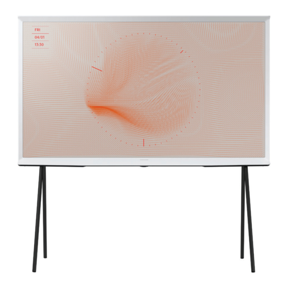
2. Product specifications 2. Product Specifications 2-1. Product information Model QN55LS01RAF * W : Width H : High D : Depth Front View * W : Width H : High D : Depth Detail View Color Front : WHITE / Stand : BLACK... - Page 11 2. Product specifications Model QN55LS01RAF Body 49.4 x 29.5 x 8.7 inches (1254.9 x 748.3 x 221.0 mm) Dimensions 55" (W x H x D) With Stand 49.4 x 48.7 x 19.0 inches (1254.9 x 1237.4 x 482.8 mm) Without Stand 57.5 lbs (26.1 kg)
-
Page 12: Product Specification
Dolby Digital Plus Dialog Enhancement Sound Output (RMS) Speaker Type Woofer Multiroom Link Blutooth Audio Smart Service Samsung SMART TV Smart US English, Korean, UK English, French, Bixby German, Italian, Spanish (features vary by language) Far-Field Voice Interaction Works with Google Assistant... - Page 13 2. Product specifications Item QN55LS01RAFXZA SmartThings Universal Guide Gallery Convergence TV to Mobile - Mirroring Mobile to TV - Mirroring, DLNA NFC on TV Yes (Sound Mirroring) 360 Video Player Seamless Setup App Casting Bluetooth Low Energy WiFi Direct TV Sound to Mobile Sound Mirroring Tuner/Broadcasting Digital Broadcasting...
- Page 14 2. Product specifications Item QN55LS01RAFXZA Motion Detection (The Frame) Ambient Mode Ambient Mode Brightness/Color Sensor Brightness Sensor Portrait Mode Instant On Processor Quad-Core Learn menu screen(US English)/ SeeColors/ Negative colors/ Grayscale/ Caption moving/ Voice Guide(US Accessibility English)/ Enlarge/ High Contrast/ Learn TV Remote(US English)/ Multi-output Audio Digital Clean View...
-
Page 15: Accessories
The part code for some accessories may differ depending on your region. • The provided accessories may vary depending on the model. • The code number can be changed, see "Exploded Views" provided on the site. Samsung Smart Remote Batteries (AA x 2) User Manual TV Power Cable Cable Guide Product Code. - Page 16 10 cm 10 cm 10 cm 10 cm 10 cm 2. Product specifications „ Arranging the cables with the cable guide Arranging the cables with the cable guide When you install your TV without a stand, arrange the cables with the cable guide as shown in the figure below: When you install your TV without a stand, arrange the cables with the cable guide as shown in the figure below: English - 7...
-
Page 17: Connect
2. Product specifications 2-4. Connect BACK OF TELEVISION ARRIÈRE DU TÉLÉVISEUR PARTE TRASERA DEL TELEVISOR OPTICAL ANT IN... -
Page 18: Viewing The Functions
NFC on TV Bouroullec Design Place your mobile device on The Serif to connect and The Serif is a collaboration between Samsung and enjoy your mobile contents on TV. Ronan & Erwan Bouroullec both the exterio design, as well as the contents and overall experience. - Page 19 2. Product specifications „ Ambient Mode Your screen doesn’t have to be black when it’s turned off. Ambient Mode serves up beautiful images and useful information you want to see, with a range of choices and settings that make it simple to transform your TV screen and use it in new ways.
- Page 20 2. Product specifications „ Metal Floor Stand A new black metal floor stand of The Serif adds another level of sophistication to The Serif’s iconic design TV. The stand blends naturally with the room environment and lets you easily position The Serif anywhere in your space. „...
- Page 21 „ Color Volume 100% Samsung’s Quantum Dot technology of 2019 The Serif lets you see what you’re supposed to see. It uses nano-sized quantum dots to produce 100% color volume, so even if the scene is exceptionally bright or dark you’ll get the realistic images you expect.
- Page 22 2. Product specifications „ NFC on TV Search less, enjoy more. QLED’s Universal Guide helps you find your favorite content quickly and easily. It learns what you like and curates everything in one place. Step 01 Step 02 With the TV screen off, place your mobile device on top Your mobile will connect to the TV via NFC.
- Page 23 Availability of the feature may vary by region. Check before use. The Serif even lets you talk to it using the power of Samsung Bixby. Controlling your TV with your voice is just the beginning of what it can do. Ask Bixby and get more.
-
Page 24: Quick Guides
Connect the Samsung Smart Remote to your TV to operate the TV. When you turn on the TV for the first time, the Samsung Smart Remote pairs to the TV automatically. If the Samsung When you turn on the TV for the first time, the Samsung Smart Remote pairs to the TV automatically. If the Samsung... - Page 25 2. Product specifications „ Using Smart Hub Connect to Smart Hub for apps, games, movies, and more. Enjoy the multiple functions provided by Smart Hub simultaneously on a single screen. NOTE • The image on your TV may differ from the image above depending on the model and geographical area. When you press the button on your remote control, you can use the following functions and features.
- Page 26 TV is turned off, the TV turns on in Ambient Mode. If you use a remote control other than the Samsung Smart Remote, there may be restrictions to entering Ambient mode. Because this function is a QLED TV-specific function, it may not be supported depending on the model.
- Page 27 If you press the button when the TV is turned off, the TV turns on in Ambient Mode. If you use a remote control other than the Samsung Smart Remote, there may be restrictions to entering Ambient Mode. Ambient Mode browser screen NOTE •...
- Page 28 This function may not be supported depending on the geographical area. • Photo Allows you to set a photo stored in your mobile device or Samsung Cloud as the wallpaper of the Ambient Mode screen. To import photos from your mobile device or Samsung Cloud, use the SmartThings app on your mobile device.
- Page 29 2. Product specifications „ Shortcuts You can easily use the contents of Sources without running a series of commands. To display the Shortcuts menu screen, press and hold the button for 1 second or more. To return to the TV mode, press the button.
- Page 30 £ Talking with Bixby using buttons You can also make a conversation with Bixby using the Samsung Smart Remote buttons. Press and hold the button on your Samsung Smart Remote, say a command, and then release the button. The TV recognises the voice command.
- Page 31 ID. Sign in to your account with your voice, that is, your registered voice ID. If you are signed out of your Samsung account, select My Profile to sign in.
- Page 32 2. Product specifications All Services You can learn the voice commands that let you use Bixby in various situations. Use the directional buttons to move to the desired command, and then press the Select button. You can operate the TV with various voice commands. View Tutorial The popup window on using Bixby appears.
-
Page 33: Nfc On Tv Function
03 Using the NFC on TV function 2. Product specifications 2-5-3. NFC on TV function You can use the NFC on TV function to listen to your mobile device sound through the TV speaker. You can use the NFC on TV function to listen to your mobile device sound through the TV speaker. 1. -
Page 34: The Remote
• The images, buttons, and functions of the Samsung Smart Remote may differ depending on the model. the TV. • The Universal Remote function operates normally only when you use the Samsung Smart Remote that comes with the TV. (Power) (Bixby) Press to turn the TV on or off. - Page 35 When you turn on the TV for the first time, the Samsung Smart Remote pairs When you turn on the TV for the first time, the Samsung Smart Remote pairs to the TV to the TV automatically. If the Samsung Smart Remote does not pair to the TV automatically.
-
Page 36: Using The Tv Controller
• Noise may occur temporarily when the TV communicates with mobile devices. You can also start the Initial Setup using the TV's menu ( > Settings > General > Reset). Follow the instructions displayed on the Initial Setup screen and configure the TV's basic settings to suit your viewing environment. -
Page 37: Supported Subtitles
2. Product specifications 2-6. Supported subtitles „ Subtitle formats Name Format MPEG-4 Timed text .ttxt SAMI .smi SubRip .srt SubViewer .sub Micro DVD .sub or .txt SubStation Alpha .ssa Advanced SubStation Alpha .ass SMPTE-TT Text .xml „ Video formats with subtitles Name Format Xsub... - Page 38 2. Product specifications „ Supported music formats and codecs File extension Format Codec Note *.mp3 MPEG MPEG1 Audio Layer 3 *.m4a *.mpa MPEG4 *.aac *.flac FLAC FLAC Supports up to 2 channels *.ogg Vorbis Supports up to 2 channels WMA is supported up to 10 Pro 5.1 channels. *.wma WMA lossless audio is not supported.
-
Page 39: Disassembly And Reassemble
This section of the service manual describes the disassembly and reassembly procedures for the LED TV. 1. Disconnect the LED TV from the power source before disassembly. 2. Follow these directions carefully. Use the Samsung Service tool to disassemble the cabinet • Recommend to use the Samsung Service too... - Page 40 3. Disassembly and Reassemble Description & Screws Picture Description Remove clean back by gently pulling the bottom. Carefully loosen the screws to remove bottom stand bracket from the body. Screws 6003-001001 SCREW-TAPTYPE : M3 x L8, ZPC(BLK) • 43 inches B/S/BOT+B/S/L/REAR : 6EA ( ) B/S/BOT+C/REAR : 12EA ( •...
- Page 41 3. Disassembly and Reassemble Description & Screws Picture Description Use Open Jig to a gap where arrow is pointing to detach rear cover from its front. Use Open Jig follwing the direction in right Jig Direction order. 1→2→3. Open Jigs BN81-14946A Draw rear cover slowly upwards, so that cable connects Jog to Function cable is not damaged.
- Page 42 3. Disassembly and Reassemble Description & Screws Picture Description Remove screws to detach NETWORK-WLAN NETWORK-WLAN CLIENT CLIENT/NETWORK-NFC Holder. NETWORK-NFC • LEAD CONNECTOR-SUB ASSY Screws 6003-000282 SCREW-TAPTYPE : M3 x L8, ZPC(BLK) • H/R/TOP+C/FRONT : 5EA Remove screws to detach ASSY BOARD P-FUNCTION.
- Page 43 3. Disassembly and Reassemble Description & Screws Picture Description Remove the ASSY PCB MAIN. • Gently lift up (Top Right corner) to release the lock. 1 Lift up (2EA) Locking 2 Mounting slots (4EA) Fixing Hole • Use both hands to hold the board and slide to the left to release the board.
- Page 44 3. Disassembly and Reassemble Description & Screws Picture Description • 55" • Gently lift the edge to unlock the SMPS board. 1 Lift up (2EA) Locking 2 Mounting slots (5EA) Slide to the Right to release the board Fixing Hole Remove the board by holding it with both hands and sliding it to the Right...
-
Page 45: Troubleshooting
4. Troubleshooting 4. Troubleshooting 4-1. Function Control Operation <To CN1501 Main Board> <Standby LED Status> <Function Switch> CN1501 (FUNCTION & IR) 3.3Vdc to 2.5Vdc (Effective DC) r A3.3V_PW SENSOR_SCL_I2C l 3.3Vdc (Effective DC) SENSOR_SDA_I2C KEY_INPUT1 3.3Vdc (Effective DC) r l 1.8dc to 0V with command KEY_INPUT2 LED_STB_OUT l 1.7Vdc STBY... -
Page 46: Power
4. Troubleshooting 4-2. Power 4-2-1. TV POWER STANDBY • 55 inches_SMPS Board CNM801 Main Connector (POWER) FUSE CNM801 (Main Connector) ANA_DIM A13V_PW OD ON/OFF A13V_PW BLU_PWM A13V_PW Power_On/Off A13V_PW TV POWER STANDBY TEST : 1. TV in Standby Check Standby LED Indicator 2. -
Page 47: Tv Power On Sequence
4. Troubleshooting 4-2-2. TV POWER ON SEQUENCE • 55 inches_SMPS Board CNM801 Main Connector (POWER) FUSE CNM801 (Main Connector) ANA_DIM A13V_PW OD ON/OFF A13V_PW BLU_PWM A13V_PW Power_On/Off A13V_PW Power TV POWER ON SEQUENCE TEST : 1. Power TV On 9 Power_On/Off (pin 8 ) .2Vdc (when off) changes to 3.3Vdc (on) NOTE •... -
Page 48: Backlight
4. Troubleshooting 4-2-3. BACKLIGHT • 55 inches_SMPS Board CNM801 Main Connector (POWER) FUSE CNM801 (Main Connector) ANA_DIM A13V_PW OD ON/OFF A13V_PW BLU_PWM A13V_PW Power_On/Off A13V_PW Backlight Backlight Test : 1. Activate Backlights Test : Disconnect Lead Cable from Main to Power supply CNM801. TV Screen for active backlight LEDs. - Page 49 4. Troubleshooting BACK LIGHT DIMMING PROBLEMS: • Go to Menu £ Picture £ Backlight and vary level (0 – 20) • If no backlight changes are observed: Panel Connector minus (-) pin voltages and P-DIM voltages CNM801 while changing backlight level while changing backlight level.
-
Page 50: Video
4. Troubleshooting 4-3. Video 4-3-1. Customer Picture „ MAIN/T-CON BOARD Main Section Pre-FRC (T-CON) Post FRC (T-CON) Results Problem Picture Test Do you still see the problem in the test photo? Show Again • Check Signal Source Picture Test and other inputs If the Self Diagnosis Picture Test is OK, your TV may not have a problem. -
Page 51: Check Test Patterns
4. Troubleshooting 4-3-2. Check Test Patterns • ENTER : Factory mode Test Pattern £ £ Main Board Muse-M Scaler Pattern / US Post Pattern FRC Pre Test Pattern FRC Post Test Pattern T-CON SoC TCON Test Pattern [Factory Mode] 1. Verify "Scaler Pattern" and "US Post Pattern" 2. -
Page 52: Main/T-Con Board
4. Troubleshooting 4-3-3. MAIN/T-CON BOARD • Main Section PRE FRC Section POST FRC Section T-CON Section £ PANEL £ £ £ „ Main Section Customer Picture Test 1 Mute > 1 > 4 > 7 > Mute Video Operation Generated on Main Section. •... - Page 53 4. Troubleshooting „ POST FRC Section Customer Picture Test 3 Video Operation Generated at Post FRC Section. • If OK: Replace Main/T-Con Board • If Noisy: Mute £ 3 £ 6 £ 9 £ Mute „ T-CON Section Mute > 3 > 6 > 9 > Mute [May not be available for Larger models over 70 inches.] Video Operation Generated at T-CON Section.
- Page 54 4. Troubleshooting „ PANEL • Check Panel 1. If Noisy Video: Panel (defective). 4-10...
-
Page 55: Audio
4. Troubleshooting 4-4. Audio • Source Main Board/T-CON Speakers £ £ „ Source • No TV Sound Menu £ Audio £ Speaker Settings set to TV Speaker • Noisy / Distorted TV Audio Customer Menu £ Support £ Sound Test - If Sound Test FAILS : (Missing / Noisy Audio) Speakers (compare resistance/quality) - Compare audio level out to speakers with... -
Page 56: Network
4. Troubleshooting 4-5. Network <TV> <Router> <Internet> „ TV to Router "Failure" 9 Check Network Status Check Network Status (TV Router Internet) Wired & Wireless MAC Address in Customer Support Menu. • No Wired MAC Address: Replace Main Board. • No Wireless MAC Address: Module cabling &... -
Page 57: Smart Hub
If it fails both Manual & Auto problem is ISP or Router. „ ISP Blocking • If it Fails: Internet Service Provider is Active. With DNS setting at 8888. With Hot Spot. „ Samsung Server Test • If it Fails: Network Status. • If OK: Reset Smart Hub. - Page 58 4. Troubleshooting For Netflix Operation/Connection Issues: 9 Check Certificate & Netflix ESN Status in Factory Mode. • If Certificate and ESN exists, "CO", "NfO", change the 8.8.8.8 • If Certificate is missing, "C/" replace the TV’s Main Board. • If ESN number is missing: NF/ do not replace the Main Board. Reset TV Clock and check for correct Time &...
-
Page 59: Bluetooth / Wifi Module
5 Vdc 5 Vdc WIFI_WOW 3.3 Vdc 3.3 Vdc BTWIFI_NRESET 3.3 Vdc 3.3 Vdc Contact Samsung < - Wired MAC Address : xx:xx:xx:xx:xx:xx Missing or Error : Replace Main Board. - Wireless MAC Address : xx:xx:xx:xx:xx:xx - Bluetooth Address : xx:xx:xx:xx:xx:xx... -
Page 60: Replacing Main Board
4. Troubleshooting 4-8. Replacing Main Board When replacing Main Board, certain values needs to be manually input in Factory menu to complete the replacement. „ Steps to Replace Main Board 1. Enter Factory Menu (Use Factory Remote only). • Power TV on : Select TV Source Info/Factory Option... - Page 61 4. Troubleshooting Writing Type • For Quick Entry of Type. 1. Confirm Type from Option Byte Table for your TV. Home Updates Exit 2. Select Writing Type. Factory Reset "Set Panel Type" appears. Type 55A1AU0RR 4. Enter exact Model Type using cursors. Writing Type 5.
- Page 62 4. Troubleshooting SW Model • Check Label Rating of the TV(located on the Rear Cover). - SW Model is digits after "/" in Version No. - Choose same SW Model code from the list. Home Updates Exit Factory Reset Type 55A1AU0RR Writing Type Local Set...
- Page 63 4. Troubleshooting Model Code • For Quick Entry of Model Code. 1. Confirm Model Code from Option Byte Table for your TV. Home Updates Exit 2. Select Model Code. Factory Reset "Set Model Code" appears. Type 55A1AU0RR 4. Enter exact Model Code using cursors. Writing Type 5.
-
Page 64: Factory Mode
„ Setting TV into Factory Mode Factory Remote 1. Power TV ON. 2. Select TV Source. Info → Factory. 4. Use MENU for return. AA81-00243A Samsung IR Remote 1. TV Power Standby. 2. Press as follows. • Remote Button NTSC MUTE POWER INFO MENU... - Page 65 4. Troubleshooting Setting Option Bytes 1. Enter Factory Mode with Service Remote (only). 2. Check Option Byte Table located on GSPN (Fast Track or Tips). 3. Select Option. 4. Select each item to change. 5. Can Use new Writing Type to enter model (if entered wrong it will not change.) 6.
- Page 66 4. Troubleshooting „ SVC £ Test Patterns Main Board Muse-M Scaler Pattern / US Post Pattern FRC Pre Test Pattern FRC Post Test Pattern T-CON SoC TCON Test Pattern [Factory Mode] 1. Verify "Scaler Pattern" and "US Post Pattern". Scaler Pattern 2.
- Page 67 4. Troubleshooting „ SVC £ Info £ ER Count • WD Count: Watch Dog (Hardware related issue). • AR Count: Auto Reset (software (i.e. Apps) related. 9 important Error Count Status Screen. • Verify each item listed. 4-23...
- Page 68 4. Troubleshooting „ Factory Mode £ Control £ EDID 1. Remove ALL HDMI connections. 2. Factory Mode → Control → EDID. (→ Enter Key) Option EDID Control Sub Option Debug Hotel Option Shop Option ADC/WB Asia Option Advanced Sound 3. Select EDID/OFF to ON. (→ Right Arrow Key) EDID ON/OFF 4.
-
Page 69: Factory Mode Adjustments
4. Troubleshooting 4-10. Factory Mode Adjustments 4-10-1. Entering Factory Mode 1. To enter [Service Mode] press the remote-control keys in this sequence : With Consumer Remote (IR Remote) Remote Button : NTSC POWER OFF MUTE POWER ON POWER OFF INFO MENU MUTE POWER ON... -
Page 70: Detail Factory Option
4. Troubleshooting 4-10-2. Detail Factory Option NOTE If you replace the main board with new one, please change the factory option as well. The options you must change are "Type". „ QN55LS01RAFXZA • PANEL / SMPS / MAIN Information Side Version FA01 PANEL SMPS... -
Page 71: Factory Data
4. Troubleshooting 4-10-3. Factory Data „ Option Factory Menu Name Data Range Factory Reset Type 55" 55A1AU0RR FA01 Writing Type Local set SW Model LS01R Model Code QN55LS01RAFXZA TUNER NTSC,ATSC Ch Table NONE MRT Option Engineer Option „ Control Factory Menu Name Data Range EDID... - Page 72 4. Troubleshooting Factory Menu Name Data Range OPTION_SWU RF Remocon Support CDD mode … DPMS Support T-CON Device Muse-M RM Server Type Operating LMF LEAVE THRESHOLD LMF TRIM THRESHOLD LMF TERM THRESHOLD EOS Click BP PMS Reset FAnet Thread CI CPLD Version ACM_MC UNIQUE TRIPLET FS_FAV...
- Page 73 4. Troubleshooting Factory Menu Name Data Range Music Mode External Source Eco Solution Cloning Shop Option Exhibition Mode Peak Mode Metadata Shopmode Picture Reset Asia Option Unbalance AF Level adjust TX Power Level Mono Last Memory H Shaking SOUND High Devi *If the broadcast signal is not good, TV will complement the characteristics of the signal (most use when weak signal comes from the...
- Page 74 4. Troubleshooting Factory Menu Name Data Range Speaker EQ Bottom Checksum NONE Wall Filter Type SRS Tuning Parm SPDIF PCM Gain AudioDock BT Delay 3D_Glass BT delay Mic Scale India Sound Speaker Delay Normal NTV CU Delay NORMAL Lipsync Inx Lipsync Checksum 0x4972 Lipsync USB Test...
- Page 75 4. Troubleshooting Factory Menu Name Data Range AP Vx1 Value N Vx1 SSC ON/OFF N Vx1 Value FRC Vx1 SSC ON/OFF FRC Vx1 SSC Period FRC Vx1 SSC Modulation FRC LVDS ON/OFF FRC LVDS SSC MFR FRC LVDS SSC MRR FRC DDR SSC ON/OFF FRC DDR SSC Period FRC DDR SSC Modulation...
- Page 76 4. Troubleshooting Factory Menu Name Data Range TCON TCON_TEMP READ TEMP LAST 6000 DCC VERSION TCON Demura Bypass TCON FDisplay Panel Code 1 Panel Code 2 Panel Revision Panel Menu Week Panel S/N 1 Panel S/N 2 Panel S/N 3 Panel S/N 4 MPEG Margin H.264 Margin...
- Page 77 4. Troubleshooting Factory Menu Name Data Range CES ATSC 3_0 CES OOBE MVPD SUPPORT BT DUT BT Throughput Reproduce Module 21_9 L-DETECT STABLE TIME L-DETECT UNSTABLE TIME L-DETECT CAPTION THRESHOLD L-DETECT RAGION THRESHOLD L-DETECT B-LEVEL THRESHOLD L-DETECT USB SUPPORT DB Download MRT Option Dump Failure Picture Data Dump...
- Page 78 4. Troubleshooting Factory Menu Name Data Range CLK TERM DURATION 300ms HDMI FLT CNT SIG HDMI FLT CND SIG2 HDMI FLT CNT LOS UNSTABLE BAN CNT 1250ms HDMI ROBIN HDMI Callback HDMI CTS Thld HDMI CTS Cnt1 HDMI EQ HDMI Write Type HDMI Switch DVI SET TIME H Write...
- Page 79 4. Troubleshooting Factory Menu Name Data Range Test Pattern Scaler Pattern US Post Pattern FRC Pre Pattern FRC Post Pattern SOC TCON Pattern SOC TCON Pattern Level FRC OSD Pre Pattern FRC OSD Post Pattern FRC2 Pre Pattern FRC2 Post Pattern SOC TCON2 Pattern SOC TCON2 Pattern Level Upgrade...
- Page 80 4. Troubleshooting Factory Menu Name Data Range NTV CU UPDATE UD LDC PROFILE UPGRADE Pic Data USB Update Audio Data USB Update Eco Data USB Update CI CPLD Upgrade SC ADK Upgrade Other Setting Delete S/N IPERF Stopped Expert CAL Data Backup …...
- Page 81 4. Troubleshooting Factory Menu Name Data Range PC Calibration HDMI Calibration ADC Result 1st_Y_GH 1st_Y_GL 1st_Cb_BH 1st_Cb_BL 1st_Cr_RH 1st_Cr_RL 2nd_R_L 2nd_G_L 2nd_B_L 2nd_R_H 2nd_G_H 2nd_B_H White Balance R-Offset G-Offset B-Offset R-Gain G-Gain B-Gain WB-W2_R_Offset WB_W2_B_Offset WB_W2_R_Gain WB_W2_B_Gain WB_N_R_Offset WB_N_B_Offset WB_N_R_Gain WB_N_B_Gain MGA On/Off R1_Gain...
- Page 82 4. Troubleshooting Factory Menu Name Data Range B2_Gain R3_Gain G3_Gain B3_Gain R4_Gain G4_Gain B4_Gain R5_Gain G5_Gain B5_Gain R6_Gain G6_Gain B6_Gain R7_Gain G7_Gain B7_Gain R8_Gain G8_Gain B8_Gain R9_Gain G9_Gain B9_Gain R10_Gain G10_Gain B10_Gain SPI White Balance SPI White Balance On/Off SPI R-Offset SPI G-Offset SPI B-Offset SPI R-Gain...
- Page 83 4. Troubleshooting Factory Menu Name Data Range SPI W2 Rgain SPI W2 Bgain SPI W2 Roffset SPI W2 Boffset SPI MGA WB Data to SPI „ Advanced 4-39...
-
Page 84: Av Control Tabe
4. Troubleshooting 4-11. AV Control Tabe Control Item Cmd1 Cmd2 Cmd3 Value General Power Power 0x00 0x00 0x00 0x00 0x01 0x02 Volume Direct 0x01 0x00 0x00 (0~100) 0x01 0x00 Down 0x02 0x00 Mute 0x02 0x00 0x00 0x00 Direct 0x04 Continuous 0x03 0x00 0x01... - Page 85 4. Troubleshooting Control Item Cmd1 Cmd2 Cmd3 Value PICTURE BackLight(CellLight) 0~20 0x01 0x00 (0~20) Contrast 0~100 0x02 0x00 (0~100) Brightness 0~100 0x03 0x00 (0~100) Sharpness 0~100 0x04 0x00 (0~100) Color 0~10 0x05 0x00 (0~100) Tint 0x06 0x00 (0~100) Advanced Settings Black Tone 0x07 0x00...
- Page 86 4. Troubleshooting Control Item Cmd1 Cmd2 Cmd3 Value PICTURE Advanced Settings Color Space Custom Cyan 0x04 Color Magenta 0x05 Color Space Custom 0~100 0x13 0~100 Color Red Value Color Space Custom 0~100 0x14 0~100 Color Green Value Color Space Custom 0~100 0x15 0~100...
- Page 87 4. Troubleshooting Control Item Cmd1 Cmd2 Cmd3 Value PICTURE Film Mode Auto2 0x02 Cinema Smooth 0x03 Auto Motion Plus 0x06 0x00 Clear 0x01 Standard 0x02 Smooth 0x03 Custom 0x04 Blur Reduction 0x0b 0x01 value Judder Reduction 0x02 value LED Clear Motion 0x03 0x00 LED Clear Motion...
- Page 88 4. Troubleshooting Control Item Cmd1 Cmd2 Cmd3 Value PICTURE Screen Adjustment Position Position3 0x02 Position4 0x03 Reset Picture Reset Picture 0x0d 0x0b 0x00 0x00 3D Mode 0x0e 0x0c 0x00 0x00 2D->3D 0x01 Side By Side 0x02 Top Bottom 0x03 Line By Line 0x04 Vertical Line 0x05...
- Page 89 4. Troubleshooting Control Item Cmd1 Cmd2 Cmd3 Value PICTURE Sound_Select_ 0x01 Channel_Up 0x05 0x00 Channel_Down 0x01 Sound Sound Mode Standard 0x0c 0x00 0x00 0x00 Music 0x01 Movie 0x02 Clear Voice 0x03 Amplify 0x04 Equalizer Balance 0x01 0x00 (0~20) 100hz 0x01 (0~20) 300hz 0x02...
- Page 90 4. Troubleshooting Control Item Cmd1 Cmd2 Cmd3 Value Sound TV Installation Type Stand 0x0c 0x00 0x00 Wallmount 0x01 Audio Delay Dealy Value (0~250) 0~250 0x0d 0x00 (0x00~0xFA) Key Generation *Refer for 0x0d 0x00 0x00 Table Show/Hide Control Show 0x0e 0x00 0x00 0x00 Hide...
-
Page 91: Updating The Tv's Software
£ £ After downloading the update file from the Samsung website and storing it on a USB device, connect the USB device to the TV to update. To update using a USB device, download the update package from Samsung.com to your computer. Then, save the update package in the USB device's top-level folder. -
Page 92: Wiring Diagram
5. Wiring Diagram 5. Wiring Diagram 5-1. Wiring Diagram • 55 inches WiFi CMM801 CN1502_SERIF CN201_NQ70 SMPS TV Board CN1301_UT CN1300 CN1501 CN1306 ACN01_14P Function Speaker • 55 inches_Inner... - Page 93 5. Wiring Diagram „ Cables NOTE • The image may differ with the specific model and area. • The code number can be changed, see "Exploded Views" provided on the site. • 55 inches WiFi LEAD CONNECTOR-SUB ASSY (10P) (6P) LEAD CONNECTOR-SUB ASSY CMM801 CN1502_SERIF...
- Page 94 5. Wiring Diagram Part Name & Connection Part Spec Code No. LEAD CONNECTOR-SUB ASSY 10P/L800 55" BN39-02473C MAIN - Combo LEAD CONNECTOR-SUB ASSY 12P/L500 55" BN39-02482A MAIN - Function LEAD CONNECTOR-SUB ASSY 6P/L500 55" BN39-02488B MAIN - NFC...
-
Page 95: Connector
5. Wiring Diagram 5-2. Connector 5-2-1. Main Board LEAD CONNECTOR-DIMMING CN1502_SERIF (6P) (NFC) CN1308 (USB2) CN201_NQ70 (POWER) CN1307 (USB1) LEAD CONNECTOR-POWER (12P) OP1853 (OPTICAL) CN2002 (HDMI4) CN2001 (HDMI3) CN1301_UT CN1902 (USI-T RIGHT) (HDMI2) (96P) FFC CABLE CN1901 (HDMI1) CN1300 CN1803_EX (USI-T LEFT) (EX-LINK) (96P) - Page 96 5. Wiring Diagram CN2002 (HDMI IN4) CN1901 (HDMI IN1) HDMI4_RX2+_HDMI HDMI1_RX2+_HDMI HDMI4_RX2-_HDMI HDMI4_RX1+_HDMI HDMI1_RX2-_HDMI HDMI1_RX1+_HDMI HDMI4_RX1-_HDMI HDMI1_RX1-_HDMI HDMI4_RX0+_HDMI HDMI1_RX0+_HDMI HDMI4_RX_CLK+_IN_ HDMI1_RX_CLK+_IN_ HDMI4_RX0-_HDMI 10 HDMI1_RX0-_HDMI 10 HDMI HDMI HDMI4_RX_CLK-_IN_ HDMI1_RX_CLK-_IN_ HDMI HDMI ARC_SINGLE HDMI4_SCL_DDC HDMI4_SDA_DDC HDMI1_SCL_DDC HDMI1_SDA_DDC HDMI4_INS_DET HDMI4_5V_PW HDMI1_INS_DET HDMI1_5V_PW HDMI4_HPD HDMI1_HPD CN2001 (HDMI IN3)
- Page 97 5. Wiring Diagram ACN01_14P (AMP) TWT_R+ TWT_R- MID_R+ MID_R- N.C. N.C. TWT_L+ TWT_L- MID_L+ MID_L- WF_L+ WF_L- N.C. N.C. CN201_NQ70 (POWER) A13V_PW A13V_PW SW_POWER_OUT A13V_PW PWM_DIMMING_OUT1 A13V_PW 10 OVD_ONOFF_LD_SDA_I2C N.C. ANA_DIMMING...
- Page 98 5. Wiring Diagram CN1301_UT (USI-T RIGHT) FB_TRDY_2 N.C. AVDD_17V_PW AVDD_17V_PW AVDD_17V_PW AVDD_17V_PW UH_CELL UL_CELL HAVDD_8.5V_PW LH_CELL LL_CELL VCCB_1.8V_PW VCCA_1.9V_PW PI_DSF_MON PORTNUM N.C. N.C. N.C. SFC1 TX_CH1_B2+_USIT TX_CH1_B2-_USIT TX_CH1_A2+_USIT TX_CH1_A2-_USIT TX_CH0_B2+_USIT TX_CH0_B2-_USIT TX_CH0_A2+_USIT TX_CH0_A2-_USIT TX_CH8_A+_USIT TX_CH8_A-_USIT TX_CH8_B+_USIT TX_CH8_B-_USIT TX_CH9_A+_USIT TX_CH9_A-_USIT TX_CH9_B+_USIT TX_CH9_B-_USIT TX_CH10_A+_USIT TX_CH10_A-_USIT...
- Page 99 5. Wiring Diagram CN1300 (USI-T LEFT) FB_TRDY_1 PANEL_3.3V_PW PANEL_3.3V_PW FB_VCOM1_2_CELL VCOM1_CELL VCOM2_CELL VCOM3_CELL VSS_OUT1_CELL VOFF_-11V_PW VGHD_30V_PW CKV1_GOA CKV2_GOA CKV3_GOA CKV4_GOA CKVB1_GOA CKVB2_GOA CKVB3_GOA CKVB4_GOA STVP1_GOA LC1_VGP1_GOA ST_GOA 23 DEMURA_SSPFRM_SPI 24 DEMURA_SSPCLK_SPI DEMURA_SSPHOLD_ DEMURA_SSPWP_SPI 27 DEMURA_SSPRXD_SPI 28 DEMURA_SSPTXD_SPI 29 DEMURA_SSPFRM_SPI 30 SFC2 TX_CH0_A1+_VX1 TX_CH0_1A-_VX1...
-
Page 100: Smps Board
5. Wiring Diagram 5-2-2. SMPS Board • 55 inches CNM801 To Main Board (12P) LEAD CONNECTOR-POWER „ SMPS Board Pin Map CNM801 ANA-DIM A13V OD_ON/OFF A13V BLU_PWM A13V POWER_On/Off A13V...
Need help?
Do you have a question about the QN55LS01RAF and is the answer not in the manual?
Questions and answers