Advertisement
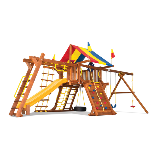
Carnival Castle
Assembly Instructions
5-70-0301
(Rev 0 - 12.14.11)
Contains Assembly, Use, and Maintenance Instructions
NOTICE: This product is intended for outdoor family domestic use only with
children ages 3 to 12. This product is not suitable for children under 36 months.
WARNING: This owner's manual contains important information about how to assemble, locate, use,
!
and maintain this playground equipment. Read this manual before you start assembly. Follow all
instructions. Be sure to educate all children who use this playground and all adult supervisors about
the rules for safe use that are contained in this manual.
Keep this Owner's Manual for future reference and to remind you of how to safely use and maintain this equipment.
RAINBOW RESERVES THE RIGHT TO MAKE CHANGES AND MODIFICATIONS TO THIS PRODUCT.
COPYRIGHT 2012 RAINBOW PLAY SYSTEMS, INC. ALL RIGHTS RESERVED
Advertisement

Related Manuals for Rainbow Play Systems Carnival Castle


Summary of Contents for Rainbow Play Systems Carnival Castle
- Page 1 Keep this Owner's Manual for future reference and to remind you of how to safely use and maintain this equipment. RAINBOW RESERVES THE RIGHT TO MAKE CHANGES AND MODIFICATIONS TO THIS PRODUCT. COPYRIGHT 2012 RAINBOW PLAY SYSTEMS, INC. ALL RIGHTS RESERVED...
-
Page 2: Table Of Contents
OWNER'S MANUAL Rainbow Play Systems, Inc. Thank you for choosing Rainbow Play Systems, Inc. Please read the instruction manual thoroughly before you start building your Carnival Castle to help ensure safe installation. Familiarize yourself with all hardware and parts to help with building your playground. -
Page 3: Rules For Safe Play
Please keep these instructions for future reference. This product is recommended for children 3 to 12 years of age. Note: This product is not intended for public use. Rainbow Play Systems, Inc. does not warranty its Residential Play Equipment subject to commercial use. - Page 4 Choosing a location for your play system When selecting your play site, always keep the child's safety in mind. Here are some recommendations that should help you achieve a safe play area. 1. The play system should be located on solid level ground free of objects that could cause injury such as, but not limited to, tree stumps, roots, and large rocks.
-
Page 5: Maintenance
TABLE 3.1 Fall Height in Feet From Which a Life Threatening Head Injury Would Not Be Expected Type of Material 6 in. depth 9 in. depth 12 in. depth Double Shredded Bark Mulch 6 ft. 10 ft. 11 ft. Wood Chips 6 ft. - Page 6 Helpful Installation Hints 1. Wear safety glasses to protect your eyes from flying wood chips when drilling or cutting. 2. Verify that all bolts and screws are secured tightly and all acorn nuts are snug (acorn nuts should be tightened to 5 foot pounds of torque). 3.
-
Page 7: Commonly Asked Questions
COMMONLY ASKED QUESTIONS Question: How do I know when Lag Bolts and other Fasteners are tightened properly? Answer: Lag Bolts and other Fasteners are tight when the head of the Lag Bolt and Washer are firmly compressed against the wood. If splintering occurs, that is an indication you are over tightening the Lag Bolts and other Fasteners. - Page 8 CIRCUS CASTLE PARTS LIST 6 @ 1 x 4 x 27 1/2" RAIL UPRIGHT 2 @ 1 x 6 x 27 1/2" RAIL UPRIGHT (3-02-0009) (3-01-0037) 1 @ 1 x 6 x 11 1/2" RAIL 1 @ 1 x 6 x 6" RAIL UPRIGHT 2 @ 1 x 6 x 27 1/2"...
- Page 9 CIRCUS CASTLE PARTS LIST 1 @ 4 x 4 x 64" MIDDLE STEP/RUNG COMBO LEG (3-06-0020) 1 @ 4 x 4 x 82" CASTLE RUNG LADDER LEG (3-06-0021) 1 @ 4 x 4 x 93" TOP JOIST w/MB HOLES (3-06-0022) 1 @ 4 x 4 x 93"...
- Page 10 WOOD ROOF ADD-ON PARTS LIST 2 @ 1 x 4 x 27 1/2" RAIL UPRIGHT 42 @ 1 x 4 x 45 1/4" ROOF BOARD (3-01-0050) (3-01-0037) 4 @ 1 x 4 x 11 1/2" FAN RAY (3-01-0051) 2 @ 1 x 4 x 17" FAN VERTICAL (3-01-0052) 4 @ 1 x 4 x 10 3/4"...
- Page 11 WOOD ROOF ADD-ON PARTS LIST 2 @ 1 x 6 x 26 1/8" NOTCHED CABIN 2 @ 1 x 6 x 53" CABIN HORIZONTAL (3-02-0022) HORIZONTAL (3-02-0021) 1 @ 1 x 6 x 18" CHIMNEY FRONT 1 @ 1 x 6 x 12 1/8" CHIMNEY BACK (3-02-0026) (3-02-0025) 2 @ 2 x 4 x 69 1/2"...
-
Page 12: Parts Identification
MONKEY BAR PARTS LIST 2 @ 4 x 4 x 93" MONKEY BAR SUPPORT LEG (3-06-0024) 1 @ 4 x 4 x 71" RIGHT MONKEY BAR ARM (3-06-0025) 1 @ 4 x 4 x 71" LEFT MONKEY BAR ARM (3-06-0026) PARTS IDENTIFICATION N168 1 @ SWING BEAM PLATE... - Page 13 PARTS IDENTIFICATION N172 N174 3 @ TTT ROD (5-41-0048) 9 @ TTT CYLINDER (5-41-0048) N173 2 @ TTT SPACER 16 @ ROCK (5-41-0048) (5-42-0030) 1 @ TIRE (5-40-0047) 1 @ RAINBOW PLAQUE (5-42-0028) 1 @ SHIP'S WHEEL 1 @TELESCOPE (5-41-0021) (5-41-0020) PARTS NOT SHOWN 1@ TARP (5-22-0238/5-22-0242)
- Page 14 H192 Phillips Pan Head Machine Screw 1/4" x 1 1/2" H183 Snap Screw #10 x 1" H184 Eye Bolt 3/8" x 3" Carnival Castle Wood Roof Hardware List F/N# DESCRIPTION DIMENSION Flat Washer 1/4" Flat Washer 3/8" Lock Washer 3/8"...
-
Page 15: Hardware
Hardware for Assembly H188 H191 H155 H154 H152 H194 H157 H158 H167 H164... - Page 16 Hardware for Assembly *NOTE: Thread length may vary from what is pictured. H135 H128 H132 H130 H129 H126...
- Page 17 Hardware for Assembly *NOTE: Thread length may vary from what is pictured. H139 H140 H100 H108 H116 H117 H119 H192 TOOLS REQUIRED FOR ASSEMBLY Tape Measure Electric Impact Gun or 1/4" 7/16" Deep Well Socket Carpenters Level and 3/8" Ratchet 1/2"...
- Page 20 Step 1 Rung Ladder Assembly 1. Place Castle Rung Ladder Leg (277) on a flat surface with the pipe holes facing up. Remove any objects from underneath the Castle Rung Ladder Leg to prevent scarring of the wood. *NOTE: Do not directly hit the wood or the Ladder Pipes (N3) with a hammer. Use Pipe Block (384) with a 3-pound (or larger) sledge hammer.
- Page 21 Step 2 Step/Rung Ladder Installation *NOTE: Pre-drill holes for all Lag Bolts with the appropriate drill bit. Use a 1/4" drill bit for 3/8" hardware (H116) (H117) (H119). 1. Attach Ladder Steps (303) to the Middle Step/Rung Combo Leg (276) and Castle Step Ladder Leg (268) using #8 Hardware (H191) or (H188).
- Page 22 Step 3 Rock Wall Board Hardware Installation *NOTE: Position Rock Wall Boards (284) (285) with the best surface down. 1. Position Rock Wall Boards (284) (285) on a flat surface and place 1/4" Hardware (H32) into the pre-drilled holes. Use a hammer or rubber mallet to gently tap the hardware into place if needed.
- Page 23 Step 4 Rock Wall Assembly *NOTE: Pre-drill holes for all Lag Bolts with appropriate drill bit. 1. Place Rock Wall Legs (273) on a flat surface with ends flush. Rock Wall Legs should be 45" apart from outside face to outside face. *NOTE: 1/4"...
- Page 24 Step 5 Main Beam, Facia, and Ladder Assembly *NOTE: Hardware should not be fully tightened at this time. 1. On a flat surface, position Main Beams (266), Angled Facias (302), and previously assembled ladders as shown and attach using 3/8" Hardware (H3) (H11) (H34) (H132). Ladders, Main Beams, and Angled Facias must be positioned as shown.
- Page 25 Step 6 Main Beam, Facia, and Ladder Assembly *NOTE: This step requires two or more people to complete. *NOTE: For ease of assembly, have all required parts and hardware in close proximity. *NOTE: Pre-drill holes for all Lag Bolts with the appropriate drill bit. *NOTE: Do not fully tighten hardware at this time.
- Page 26 Step 7 Top Joists Installation *NOTE: Do not fully tighten hardware at this time. *NOTE: 3/8" Hardware (H28) is shown in this step, but will not be installed until Step 8. *NOTE: The counter-sunk holes in Top Joists (278) and (279) must face down (as shown in INSET A).
- Page 27 Step 8 Front Beam and Upper Rope Arm Installation *NOTE: Do not fully tighten hardware at this time. 1. Attach Front Beam (271) to Top Joists (278) (279) using 3/8" Hardware (H3) (H11) (H17) (H28) (H55) and 1/2" Hardware (H4). Front Beam (271) must be located on the side of the set with the Rock Wall.
- Page 28 Step 9 Deck Installation 1. Place all Deck Boards (287) (304) (288) (305) across the Main Beams in the order shown and space Deck Boards out evenly. Pre-drilled holes should line up in the center of the Main Beams (266). 2.
- Page 29 Step 10 Facia and Center Post Installation *NOTE: Pre-drill holes for all Lag Bolts with the appropriate drill bit. 1. Position Front Facia (292) and 2 Hole Facia (291) on top of Angled Facias (302). Front Facia (292) should be located on the side of the set under the Monkey Bar Holes as shown below. 2.
- Page 30 Step 11 Rail Upright Installation *NOTE: The 17 1/4" opening for the TTT Panel must be on the side of the set away from the offset holes for the Swing Beam in the Top Joist with Swing Holes (279) (as shown in INSET A).
- Page 31 Step 12 Swing Assembly *NOTE: Half-Bucket Swing (N17) is intended for use by children ages 3-5, under adult supervision. 1. Open C-Links (N30) and Pear Links (N31). *NOTE: When closing C-Links and Pear Links, securely tighten using a crescent wrench 2.
- Page 32 Step 13 4 Chain Tire Swing Assembly 1. Attach Eye Bolts (H196) to Tire (N169) using 3/8" Hardware (H14) (H24) (as shown in Detail A). *NOTE: Make sure Eye Bolts (H196) are orientated as shown using the 12" measurement. 2. Open C-Links (N30). Divide the six Chains (N12) into groups of three Chains. Connect each group of Chains together using C-Links (N30) (as shown in Inset A).
- Page 33 Step 14 A-Frame Assembly and Swing Hanger Installation *NOTE: It is possible to modify your 3 Position Swing Beam to a 2 Position Swing Beam for use in small yards. See Step 38, page 57 for instructions on how to modify the 3 Position Swing Beam to a 2 Position Swing Beam.
- Page 34 Step 15 Swing Beam Installation 1. On the ground, place Swing Beam (346) on top of Swing Beam Block (81). Attach 45 Bracket (N170) to Swing Beam (346) through pre-drilled hole using Bolt Cup (N29), 1/2" Hardware (H4), and 3/8" Hardware (H56) (H3) (H11) (H17).
- Page 35 Step 15 Swing Beam Installation Continued from previous page: H100 H164 N171 H164 INSET A H108 INSET B N170 H100...
- Page 36 Step 16 Tire Swing Installation 1. Center Tire Swivel (N25) on the middle Deck Boards and mark the location of the mounting holes. The holes should hit towards the middle of the Deck Boards and be approximately 12" - 13" from the front edge of the Deck Boards.
- Page 37 Step 17 Rock and Rope Installation 1. Attach Rocks (N22) to Rock Wall Boards (284) (285) using 1/4" Hardware (H7) (H192) and 1/4" T-Nuts (H32) that were installed in Step 3. Use four 1/4" SAE Washers (H7) for each Rock. *WARNING: TO PREVENT THE RISK OF STRANGULATION, THREE KNOTS MUST BE TIED IN ROPE AND ROPE MUST BE SECURE AT BOTH ENDS.
- Page 38 Step 18 Tic Tac Toe Installation 1. Place Tic Tac Toe Rods (N174) into bottom Tic Tac Toe Board (267). 2. Place three Tic Tac Toe Cylinders (N172) on each Rod (N174), with a Tic Tac Toe Spacer (N173) in between each layer of Cylinders (N172). 3.
- Page 39 Step 19 Bubble Window Installation *SUGGESTION: Use wood clamps to hold Window Frame (354) pieces together during assembly. 1. On a flat surface, lay Window Frame (354) pieces in a square (as shown in INSET A) and attach using #8 Hardware (H154). 2.
- Page 40 Step 20 Ship's Wheel and Telescope Installation *NOTE: Pre-drill holes for all Lag Bolts using appropriate drill bit. 1. Position Ship's Wheel on Center Post (263) if installing the Tarp Roof or on the end of the Swing Beam if installing the Wood Roof. If installing Ship's Wheel on the Center Post, make sure lag bolt goes through the Center Post and into the Top Joist (279).
- Page 41 Step 21 Safety Handle Installation *NOTE: Use an 1/8" drill bit to drill holes 1/2" deep for #14 Hardware (H167). 1. Attach Castle Ladder Handles (N6) to Step/Rung Ladder Legs using #14 Hardware (H167). Castle Ladder Handles (N6) should be approximately 18" up from the bottom face of the Ladder Legs. 2.
- Page 42 Step 22 Slide Installation 1. Center Double Wall Wave Slide (N24) in the opening provided and attach to Deck Boards using 1/4" Hardware (H7) and #14 Hardware (H164) (as shown in DETAIL A). Wave Slide should sit approximately 4" to 5" back from the Angled Facia (302). H164 DETAIL A...
- Page 43 Step 23 Tarp Installation *NOTE: Skip to Step 24 if installing Wood Roof. 1. Evenly spread Tarp (N41) over the top of Tarp Board (265) and 2 Hole Facias (264) with the Snaps against the inside. 2. Wrap Tarp (N41) around the bottom side of 2 Hole Facias (264). Starting with the middle tarp snaps, gently tap each snap with a hammer to leave an indentation in the wood.
- Page 44 Step 24 Monkey Bar and Monkey Bar Support Assembly 1. Place the Right Monkey Bar Arm (281) and one Monkey Bar Support Leg (280) on a flat surface with the pipe holes facing up. Remove any objects from underneath the wood parts to prevent scarring of the wood.
- Page 45 Step 25 Monkey Bar Assembly 1. Position Monkey Bar assembly and Monkey Bar Support assembly on the ground as shown. 2. Position the two inside Monkey Bar Plates (N11) and insert 3/8" Hardware (H30) into holes. Use a hammer to gently tap hardware into holes if needed. 3.
- Page 46 Step 26 Monkey Bar Installation *NOTE: At least two people are required to complete this step. 1. Lift up entire Monkey Bar assembly and align pre-drilled holes in Monkey Bar Arms (281) (282) with pre-drilled holes in Top Joist with Monkey Bar Holes (278) and attach using 3/8" Hardware (H3) (H11) (H17) (H28) (H55) and 1/2"...
- Page 47 Step 27 Wood Roof Installation 1. Install 3/8" Hardware (H34) into pre-drilled holes in Top Joists (278) (279) by gently tapping hardware with a hammer until flush with the face of the wood. 2. Attach Left and Right Roof Supports (360) (361) to Top Joists, in the positions shown, using 3/8" Hardware (H3) (H11) (H34) (H130).
- Page 48 Step 28 Wood Roof Installation *NOTE: Holes in Roof Frame Top/Bottom Boards (306) are offset. Position board correctly as shown below. 1. Center Roof Frame Tops (306) on Roof Supports (360) (361) and attach using #8 Hardware (H152). Roof Frame Tops (306) should over-hang Peak Facias (308) by approximately 2". Roof Frame Tops (306) should form a peak without gaps between boards (as shown in INSET A).
- Page 49 Step 29 Wood Roof Installation 1. Position Roof Frame Sides (307) in locations shown and attach to Roof Boards (245) using #8 Hardware (H152). When properly assembled, outside faces of Roof Frame Top (306) and Roof Frame Sides (307) should be flush (as shown in DETAIL A). 2.
- Page 50 Step 30 Dormer Assembly 1. On a flat surface arrange Right Dormer Support (358), Left Dormer Support (357), and Fan Horizontal (355) (as shown in Inset A & B) using #8 Hardware (H154). 2. Position Fan Center (356), Fan Vertical (363) and Fan Rays (362) (as shown in Inset A & B) and attach using #8 Hardware (H194).
- Page 51 Step 31 Dormer Installation 1. Position Dormer assembly on roof. Dormer assembly should be centered horizontally and Dormer Supports (357) (358) should be flush with the bottom edge of a Roof Board (245). 2. Attach Dormer assembly to the roof through Roof Boards (245) and into Dormer Runners (380) using six #8 Screws (H152).
- Page 52 Step 32 Chimney Installation 1. On a flat surface, stand Chimney Sides (382), Chimney Back (379), and Chimney Front (378) on end as shown and attach using #8 Hardware (H194). Angled faces should be flush (as shown in INSET 2. Center Chimney Trim (329) pieces on Chimney Sides (382) and attach using #8 Hardware (H194). 3.
- Page 53 Step 33 Fan Installation *NOTE: Over-tightening screws in fan may cause wood to split. 1. On a flat surface, place the Fan Center (383), Fan Horizontal (259), and Fan Vertical (247) (as shown in INSET A and INSET B). The Fan Horizontal (259) should extend out past the Fan Center (383) approximately 17 3/4"...
- Page 54 Step 34 Swing Beam Cabin Installation 1. Position Window Trim pieces (300) (301) on the ground with the angled faces together (as shown in INSET A). Attach Window Trim pieces (300) (301) using #8 Hardware (H154). 2. From the inside of the set, attach Notched Cabin Horizontals (261) to Roof Supports (360) (361) on the Swing Beam side of the set using #8 Hardware (H194).
- Page 55 Step 35 Cabin Installation 1. On a flat surface, position Window Trim (298) and Arched Window Trim (299) in a square (as shown in INSET B) and attach using #8 Hardware (H154). 2. From the inside of the set, attach Notched Cabin Horizontal (260) to Roof Supports (360) (361) using #8 Hardware (H194).
- Page 56 Step 36 Rope Ladder Installation *WARNING: TO PREVENT THE RISK OF STRANGULATION, KNOTS MUST BE TIED IN ROPE AND ROPE MUST BE SECURE AT BOTH ENDS. ROPE MUST BE TIGHT ENOUGH THAT IT CANNOT BE LOOPED BACK ON ITSELF, AND NO MORE THAN 12"...
- Page 57 Step 37 Stake Installation *NOTE: Do not hit washer while pounding Stakes (N28) into the ground. *NOTE: Stakes must be installed as close as possible to Ladder Legs and Swing Beam Legs. *NOTE: For maximum strength, drive stakes into the ground at a slight angle. *WARNING: ALL UNDERGROUND UTILITIES MUST BE LOCATED BEFORE ANCHORING PLAY SET.
- Page 58 Step 38 2 Position Swing Beam Modification *NOTE: Be sure proper end is cut as specified in the diagrams below. 1. Cut 25 3/4" off of the outer end of Swing Beam (346) (as shown). 2. Router all sharp edges of cut end of Swing Beam (346). 3.
-
Page 59: Warranty
Some states do not allow limitations on how long an implied warranty lasts, so the above limitation may not apply to you. Rainbow Play Systems, Inc.
Need help?
Do you have a question about the Carnival Castle and is the answer not in the manual?
Questions and answers
Is the metal mounted plate on swing set supposed to move or stay stay stationary while using?