Advertisement
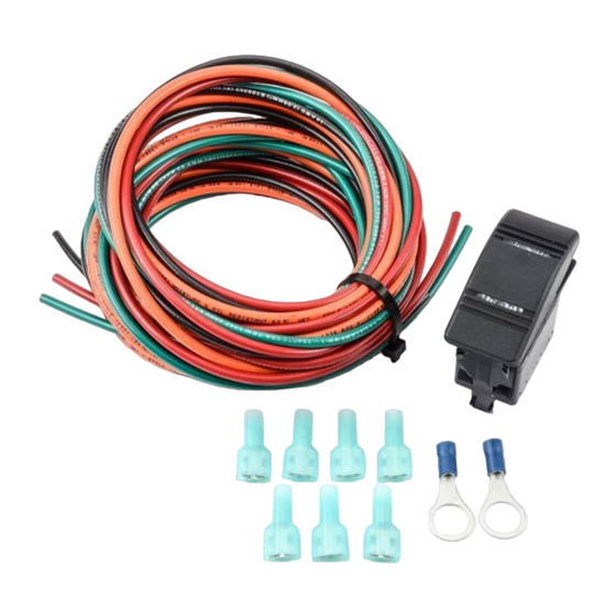
#31143 Illuminated 3-Way Switch Kit
The Flex-a-lite illuminated 3-way switch allows for
in-vehicle control of your fan. By directly connected
to the pins located on the controller, you can shut
your fan off during water crossings, or keep the fan
running at 100% power for towing up steep roads.
2
Prep & Run Wires
1. Cut a small (~2") segment off of included black wire.
Strip both ends of the wire and one end of the wire that
was cut from. Twist one end of the small segment to the
long wire, and crimp 2 of the included insulated flag
terminals to the exposed end. (Fig. 1)
NOTE: If using Cooling Control Module Part #31149,
apply previous step to the red wire.
2. Strip one end on both the orange and green wires.
Crimp an insulated flag terminal to each.
Register your product for warranty at : http://automotive.flex-a-lite.com/warranty-registration/
1
Enjoy your Flex-a-lite performance cooling product!
Create Switch Mount Location
1. Determine mounting position for the switch. Look for
a flat section of panel that is easily accessible from the
driver's seat to activate.
2. Check to make sure there are no wires or
electronics directly behind this area. You will also need
a minimum depth clearance of 1-3/4" to clear the switch
body and the wires to attach.
3. Strip one end of the included red
wire (black wire for part #31149
controller). Crimp an insulated flag
terminal to the wire.
4. Find a suitable location in the
firewall of the vehicle to pass these 4
wires through. If drilling, make sure
to use a grommet on the firewall to
prevent abrasive damage to the wire.
NOTE: If using the 3-way switch
with Flex-a-lite® Cooling Control
Module Part #31149, Turn page
Fig. 1
over for wiring diagrams.
Fig. 2
3. Mark off a rectangular hole 1-1/2" Tall x 7/8" Wide with
masking tape where you plan to mount the switch. If
you can remove this panel from the vehicle, cutting this
hole will be easier. Drill the corners of the marked
rectangle and remove the remaining material with a
small cutting blade and a file. Make sure the hole is clear
of any loose material or sharp filings.
3
Install & Test
1. Connect wires to back of plug and wire to VSC as
shown in diagram below. (FIg. 2)
NOTE: The loop from pin 2 to 5 represents the jumper
lead produced in FIg. 1.
2. Secure and cut all wires to length before connecting
to the VSC. Ring terminals are provided if you choose to
connect 12V power and ground directly to the battery.
3. After connecting all wires, confirm the function of
the switch. When the blue light is active on the switch
the fan should be in Manual ON mode. When the red
light is active on the switch the fan should be in Manual
OFF mode. Confirm Manual OFF by first allowing your
vehicle warm up. Activate the switch when your fan
begins normally cycling from the temp probe readings.
If you need further assistance, please contact tech services
at 253-922-2700 M-F 8:00am-5:00pm PST.
98143 Rev. 01-22-14
Advertisement
Table of Contents

Related Manuals for Flex-a-Lite 31143

Summary of Contents for Flex-a-Lite 31143
- Page 1 Register your product for warranty at : http://automotive.flex-a-lite.com/warranty-registration/ Enjoy your Flex-a-lite performance cooling product! #31143 Illuminated 3-Way Switch Kit Create Switch Mount Location 1. Determine mounting position for the switch. Look for 3. Mark off a rectangular hole 1-1/2” Tall x 7/8” Wide with...
- Page 2 Flex-a-lite Consolidated, 7009-45th St. Ct. E. Fife, WA 98424, Telephone No. 253-922-2700, warrants to the original purchasing user, that all Flex-a-lite products to be free of defects in material and workmanship for a period of 365 days (1 year) from date of purchase.
Need help?
Do you have a question about the 31143 and is the answer not in the manual?
Questions and answers