Table of Contents
Advertisement
Quick Links
Advertisement
Table of Contents

Related Manuals for Rohde & Schwarz TS-PIO2

Summary of Contents for Rohde & Schwarz TS-PIO2
- Page 1 ® R&S TS-PIO2 Analog/Digital IO Module 2 User Manual (?6Ö8<) 1506.7208.12 ─ 06...
- Page 2 Subject to change – Data without tolerance limits is not binding. ® R&S is a registered trademark of Rohde & Schwarz GmbH & Co. KG. Trade names are trademarks of the owners. ® The following abbreviations are used throughout this manual: R&S TS-PIO2 is abbreviated as R&S TS-PIO2.
-
Page 3: Basic Safety Instructions
Basic Safety Instructions Always read through and comply with the following safety instructions! All plants and locations of the Rohde & Schwarz group of companies make every effort to keep the safety standards of our products up to date and to offer our customers the highest possible degree of safety. Our products and the auxiliary equipment they require are designed, built and tested in accordance with the safety standards that apply in each case. - Page 4 Basic Safety Instructions Symbol Meaning Symbol Meaning Caution ! Hot surface Alternating current (AC) Protective conductor terminal Direct/alternating current (DC/AC) To identify any terminal which is intended for connection to an external conductor for protection against electric shock in case of a fault, or the terminal of a protective earth Earth (Ground) Class II Equipment...
- Page 5 Basic Safety Instructions Operating states and operating positions The product may be operated only under the operating conditions and in the positions specified by the manufacturer, without the product's ventilation being obstructed. If the manufacturer's specifications are not observed, this can result in electric shock, fire and/or serious personal injury or death. Applicable local or national safety regulations and rules for the prevention of accidents must be observed in all work performed.
- Page 6 Basic Safety Instructions 6. The product may be operated only from TN/TT supply networks fuse-protected with max. 16 A (higher fuse only after consulting with the Rohde & Schwarz group of companies). 7. Do not insert the plug into sockets that are dusty or dirty. Insert the plug firmly and all the way into the socket provided for this purpose.
- Page 7 Basic Safety Instructions 2. Before you move or transport the product, read and observe the section titled "Transport". 3. As with all industrially manufactured goods, the use of substances that induce an allergic reaction (allergens) such as nickel cannot be generally excluded. If you develop an allergic reaction (such as a skin rash, frequent sneezing, red eyes or respiratory difficulties) when using a Rohde &...
- Page 8 Basic Safety Instructions 2. Adjustments, replacement of parts, maintenance and repair may be performed only by electrical experts authorized by Rohde & Schwarz. Only original parts may be used for replacing parts relevant to safety (e.g. power switches, power transformers, fuses). A safety test must always be performed after parts relevant to safety have been replaced (visual inspection, protective conductor test, insulation resistance measurement, leakage current measurement, functional test).
- Page 9 Instrucciones de seguridad elementales Waste disposal/Environmental protection 1. Specially marked equipment has a battery or accumulator that must not be disposed of with unsorted municipal waste, but must be collected separately. It may only be disposed of at a suitable collection point or via a Rohde &...
- Page 10 Instrucciones de seguridad elementales Se parte del uso correcto del producto para los fines definidos si el producto es utilizado conforme a las indicaciones de la correspondiente documentación del producto y dentro del margen de rendimiento definido (ver hoja de datos, documentación, informaciones de seguridad que siguen). El uso del producto hace necesarios conocimientos técnicos y ciertos conocimientos del idioma inglés.
- Page 11 Instrucciones de seguridad elementales Símbolo Significado Símbolo Significado Aviso: Cuidado en el manejo de dispositivos Distintivo de la UE para la eliminación por sensibles a la electrostática (ESD) separado de dispositivos eléctricos y electrónicos Más información en la sección "Eliminación/protección del medio ambiente", punto 2.
- Page 12 Instrucciones de seguridad elementales 1. Si no se convino de otra manera, es para los productos Rohde & Schwarz válido lo que sigue: como posición de funcionamiento se define por principio la posición con el suelo de la caja para abajo, modo de protección IP 2X, uso solamente en estancias interiores, utilización hasta 2000 m sobre el nivel del mar, transporte hasta 4500 m sobre el nivel del mar.
- Page 13 Instrucciones de seguridad elementales 6. Solamente está permitido el funcionamiento en redes de alimentación TN/TT aseguradas con fusibles de 16 A como máximo (utilización de fusibles de mayor amperaje solo previa consulta con el grupo de empresas Rohde & Schwarz). 7.
- Page 14 Instrucciones de seguridad elementales Funcionamiento 1. El uso del producto requiere instrucciones especiales y una alta concentración durante el manejo. Debe asegurarse que las personas que manejen el producto estén a la altura de los requerimientos necesarios en cuanto a aptitudes físicas, psíquicas y emocionales, ya que de otra manera no se pueden excluir lesiones o daños de objetos.
- Page 15 Instrucciones de seguridad elementales Reparación y mantenimiento 1. El producto solamente debe ser abierto por personal especializado con autorización para ello. Antes de manipular el producto o abrirlo, es obligatorio desconectarlo de la tensión de alimentación, para evitar toda posibilidad de choque eléctrico. 2.
- Page 16 Instrucciones de seguridad elementales 2. Las asas instaladas en los productos sirven solamente de ayuda para el transporte del producto por personas. Por eso no está permitido utilizar las asas para la sujeción en o sobre medios de transporte como p. ej. grúas, carretillas elevadoras de horquilla, carros etc. Es responsabilidad suya fijar los productos de manera segura a los medios de transporte o elevación.
- Page 17 Quality management Certified Quality System ISO 9001 and environmental Certified Environmental System management ISO 14001 Sehr geehrter Kunde, Dear customer, Cher client, Sie haben sich für den Kauf You have decided to buy a Vous avez choisi d’acheter un eines Rohde & Schwarz Produk- Rohde &...
-
Page 18: Customer Support
Customer Support Technical support – where and when you need it For quick, expert help with any Rohde & Schwarz equipment, contact one of our Customer Support Centers. A team of highly qualified engineers provides telephone support and will work with you to find a solution to your query on any aspect of the operation, programming or applications of Rohde &... - Page 19 The Analog/Digital IO Module R&S TS-PIO2 can be operated on the R&S Com- pactTSVP and R&S PowerTSVP test platforms. The card receives its ground-free power supply from a Rear-I/O module of type R&S TS-PDC. The R&S TS-PIO2 is con- trolled by the CAN bus present in the R&S CompactTSVP and R&S PowerTSVP.
- Page 20 The Rear I/O Module R&S TS-PDC is used as a floating DC voltage source for the Analog/Digital IO Module R&S TS-PIO2. It contains two identical DC/DC converters. The following floating voltages are obtained from an input voltage of 5 VDC: ●...
-
Page 21: Safety Instructions
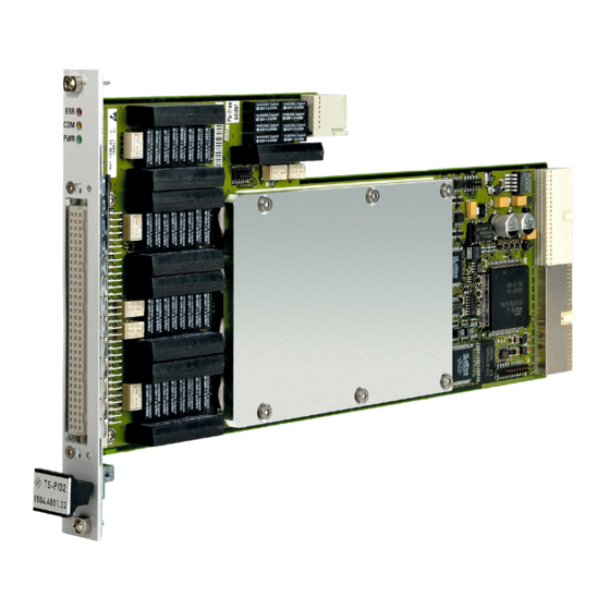
1.4 Safety instructions The R&S CompactTSVP/ R&S PowerTSVP production platform and the Analog/Digital IO Module R&S TS-PIO2 are designed so that users can operate at voltages up to 125 V. The requirements according to EN61010-1 for operation with “hazardous live” vol- tages must be observed. - Page 22 View R&S TS-PIO2 2 View Figure 2-1 shows the Analog/Digital IO Module R&S TS-PIO2 without the accompany- ing Rear I/O Module R&S TS-PDC. The Rear I/O Module R&S TS-PDC is shown in Figure 2-2. Figure 2-1: View of the R&S TS-PIO2...
- Page 23 ® View R&S TS-PIO2 Figure 2-2: View of the Rear-I/O Module R&S TS-PDC The Module R&S TS-PDC exists in 3 different models: ● Grouted in a black housing - version up to 1.8 (1157.9804.02 obsolete) ● Encapsulated in metal housing with cooling fins - version 1.9 (1157.9804.02 obso- lete) ●...
-
Page 24: Block Diagrams
Analog/Digital IO Modules R&S TS-PIO2. Figure 3-3 shows the block diagram of the Rear I/O Module R&S TS-PDC. Figure 3-1: Functional block diagram of R&S TS-PIO2 with R&S TS-PDC in the R&S PowerTSVP User Manual 1506.7208.12 ─ 06... - Page 25 ® Block Diagrams R&S TS-PIO2 Figure 3-2: Block diagram Analog/Digital IO Module R&S TS-PIO2 User Manual 1506.7208.12 ─ 06...
- Page 26 ® Block Diagrams R&S TS-PIO2 Figure 3-3: Block diagram Rear-I/O Modul R&S TS-PDC User Manual 1506.7208.12 ─ 06...
- Page 27 4 Layout 4.1 Mechanical layout of the module R&S TS-PIO2 The Analog/Digital IO Module R&S TS-PIO2 is designed as a long plug-in card for front installation in test platforms R&S CompactTSVP or R&S PowerTSVP. The front-side connector X10 is used to connect test objects. The connector X30 con- nects the module with the analog bus backplane in the R&SCompactTSVP /R&S Pow-...
- Page 28 4.2 Display elements of the module R&S TS-PIO2 Figure 4-2: Arrangement of the LEDs on the module R&S TS-PIO2 On the front side of the module R&S TS-PIO2 there are three LEDs which show the current status of the module. The LEDs have the following meaning: Table 4-2: Display elements on the module R&S TS-PIO2...
- Page 29 ® Layout R&S TS-PIO2 Mechanical layout of R&S TS-PDC The module R&S TS-PDC must always be plugged into the corresponding rear I/O slot (same slot code) of the module R&S TSPIO2 . If it is not correctly plugged in (e.g. cPCI/PXI standard modules in the front area) both modules may be destroyed.
- Page 30 ® Layout R&S TS-PIO2 Display elements of the R&S TS-PDC Module 4.4 Display elements of the R&S TS-PDC Module 4.4.1 R&S TS-PDC Version lower than 2.0 (1157.9804.02) The actual status of the module is signalized by 8 green LEDs, whereat each LED indi- cates the presence of an output voltage.
-
Page 31: Function Description
5.1 Function description of the R&S TS-PIO2 module 5.1.1 General The Analog/Digital IO Module R&S TS-PIO2 makes 16 IO channels (CH1 to CH16) available. The channels are arranged in four groups from A to D. The last output chan- nel of each group (CH4, CH8, CH12 and CH16) has special properties. - Page 32 Function Description R&S TS-PIO2 Function description of the R&S TS-PIO2 module The individual modes are described in greater detail in the following chapters. Some of the settings for a channel can be made channel-specifically or group-specifi- cally. The following illustration is a graphical representation showing the possible set- tings for channel outputs in group A.
-
Page 33: Application Examples
® Function Description R&S TS-PIO2 Function description of the R&S TS-PIO2 module 5.1.2 Application examples Figure 5-2: Independent use of input and output Figure 5-3: Switchable loads (pull-up and pull-down of digital inputs) User Manual 1506.7208.12 ─ 06... - Page 34 ® Function Description R&S TS-PIO2 Function description of the R&S TS-PIO2 module Figure 5-4: Test of „Low-Side“ outputs (OC, OD, optocoupler, switch, etc.) Figure 5-5: Test of „High-Side“ outputs (OC, OD, optocoupler, switch, etc.) User Manual 1506.7208.12 ─ 06...
- Page 35 ® Function Description R&S TS-PIO2 Function description of the R&S TS-PIO2 module Figure 5-6: Extended channel for implementing current interfaces (0.5 mA …100 mA, actuators) Figure 5-7: Evaluation of current interfaces (sensors) User Manual 1506.7208.12 ─ 06...
-
Page 36: Signal Wiring
5.1.3.1 General All signal wiring of the R&S TS-PIO2 module is performed with the aid of relays. Since relays have an operate and release time as well as a bounce time, you should wait until the signals are stable in a test program after wiring connections. Function rspio2_IsDebounced can be used to determine whether the switching processes are complete. - Page 37 ® Function Description R&S TS-PIO2 Function description of the R&S TS-PIO2 module 5.1.3.2 Module ground wiring The module ground (potential-free common reference point of IO channels, AGND) can be connected via relays with the front side connector (LO) and with each line of the analog bus (ABxy).
- Page 38 Please note that function rspio2_DisconnectAll does not open these relays! 5.1.3.6 Ground relays The R&S TS-PIO2 module has a ground relay that can be used to connect the poten- tial-free module ground (AGND) with ground (GND). User Manual 1506.7208.12 ─ 06...
- Page 39 To compensate for voltage drops in the power supply to the external load, the exten- ded channels (CH4, CH8, CH12 and CH16) of R&S TS-PIO2 can be set to external sensing. Two additional lines directly to the test object are required for this purpose.
- Page 40 ® Function Description R&S TS-PIO2 Function description of the R&S TS-PIO2 module nel and is always applied to it. Function rspio2_ConfigureChannelCurrentLimit facilitates this setting. 5.1.6 Output of static voltages In the basic state of the module, all outputs are in the „Analog“ operating mode. If nec- essary, this mode can also be selected with function rspio2_ConfigureChannelMode.
- Page 41 Function rspio2_SetAnalogWaveformMemory is used to transfer the values to the R&S TS-PIO2 module. As in the case of digital bit patterns, a maximum of 5000 values can be written to memory. If fewer values have been stored in memory than sequence control needs to generate, the last value is repeated.
- Page 42 Function Description R&S TS-PIO2 Function description of the R&S TS-PIO2 module Generation of square wave signals is independent of sequence control for recording of measurement values and of the output of digital bit patterns and arbitrary waveforms. If the output of a square wave signal is enabled for a group, the following settings can- not be modified for any channels in that group: ●...
- Page 43 ® Function Description R&S TS-PIO2 Function description of the R&S TS-PIO2 module Table 5-3: Methods for voltage measurement Method Note Single Ended The level is measured between one input (CHx_IN) and module ground (AGND or LO on the front side connector) Differential The level between two inputs is determined by taking the difference.
- Page 44 In that case, those functions return an error message. If necessary, sequence control can be switched to its basic state with the rspio2_Abort function. 5.1.14 Generating trigger signals The R&S TS-PIO2 module is capable of generating trigger signals on the following lines: Table 5-6: Trigger outputs...
- Page 45 TS-PIO2 module has just been turned on or reset by a hardware reset. 5.1.16 Excess temperature protection There are four temperature sensors on the R&S TS-PIO2 module. If one of these sen- sors reports an inadmissible temperature, the module switches off automatically. The functions for switching signals and activating outputs return an error message in this state.
- Page 46 ● 46.7 V AC peak When operating the Analog/Digital IO Module R&S TS-PIO2 above these voltage limit values, the requirements of EN61010-1 must be observed. The Analog/Digital IO Module R&S TS-PIO2 and Test System Versatile Platform R&S CompactTSVP / R&S PowerTSVP are designed for a maximum voltage of 125 V between ground-free measurement devices, analog busses, and GND.
- Page 47 Press in the module applying moderate pressure. ● The upper catch pin of the R&S TS-PIO2 module must be guided into the right hole, while the lower catch pin is guided into the left hole of the R&S Com- pactTSVP / R&S PowerTSVP housing.
- Page 48 ® Commissioning R&S TS-PIO2 Installation of the R&S TS-PDC module ● Remove the front panel from the rear side of the TSVP chassis by slackening off the screws Damaged backplane due to bent pins Bent pins may result in permanent damage to the backplane.
-
Page 49: Driver Software
A LabWindows IVI driver that supports the class IVI SWTCH is available for the func- tions of the Analog/Digital IO Module R&S TS-PIO2. The driver is a component of the ROHDE & SCHWARZ GTSL software program. All functions of the driver are docu- mented extensively in online Help and in the LabWindows/CVI Function Panels. - Page 50 Soft Panel Figure 7-1: Soft Panel R&S TS-PIO2 The operation of the Soft Panel is described in the R&S GTSL Software Description. The signal paths connections of the R&S TS-PIO2 can also be determined by the Soft Panel (Figure 7-3).
- Page 51 ® Software R&S TS-PIO2 Soft Panel Figure 7-2: Soft Panel R&S TS-PIO2 connections User Manual 1506.7208.12 ─ 06...
- Page 52 Software R&S TS-PIO2 Sample program R&S TS-PIO2 Figure 7-3: Soft Panel R&S TS-PIO2 measurement results 7.3 Sample program R&S TS-PIO2 This example connects all channels to the front connector, configures the channels and starts the output/acquisition sequence. Error handling is not considered in this sample in order to keep it easy to read.
- Page 53 ® Software R&S TS-PIO2 Sample program R&S TS-PIO2 static ViUInt16 s_digiStim[SAMPLE_COUNT]; static ViUInt16 s_digiResp[SAMPLE_COUNT]; static ViReal64 s_waveform[SAMPLE_COUNT]; static ViReal64 s_measResult[SAMPLE_COUNT]; int main (int argc, char *argv[]) ViSession vi; ViStatus status; ViReal64 result; ViChar chName[5], ch1[8], ch2[8]; ViInt32 idx; open a session to the device driver. The resource descriptor depends on the slot number of the module and must be adapted to the target system.
- Page 54 ® Software R&S TS-PIO2 Sample program R&S TS-PIO2 RSPIO2_VAL_TRIG_SEQ_START, 0, RSPIO2_TRIG_MASK_XTO1); /* configure module earth tied (connect AGND to GND) */ status = rspio2_ConfigureGround (vi, VI_TRUE); /* connect AGND to front connector */ status = rspio2_Connect (vi, "AGND", "LO"); /* connect all output channel to front connector */ for (idx = 1;...
- Page 55 ® Software R&S TS-PIO2 Sample program R&S TS-PIO2 /* configure channel 16 to mode waveform */ status = rspio2_ConfigureChannelMode (vi, "CH16", RSPIO2_VAL_CH_MODE_WAVEFORM); /* configure current limit for the extented channels */ status = rspio2_ConfigureChannelCurrentLimit (vi, "CH4", 10.0e-3); status = rspio2_ConfigureChannelCurrentLimit (vi, "CH8", 10.0e-3);...
- Page 56 ® Software R&S TS-PIO2 Sample program R&S TS-PIO2 ViInt32 maxTime = SAMPLE_COUNT * SAMPLE_INTERVAL * 1000; status = rspio2_FetchDigital (vi, maxTime, SAMPLE_COUNT, s_digiResp, & actualPoints); status = rspio2_FetchAnalog (vi, maxTime, SAMPLE_COUNT, s_measResult, & actualPoints); /* disable square wave generation */ status = rspio2_SquareWaveEnabled (vi, 0x4, 0x0);...
-
Page 57: Power On Test
Description PWR LED (green) on All power supply voltages are present PWR LED (green) off At least one power supply of module R&S TS-PIO2 or module R&S TS-PDC is not present ERR LED (red) off No error is present ERR LED (red) is lit or... - Page 58 TS-PIO2 TSVP self-test 8.3 TSVP self-test As part of the TSVP self test, an extensive test of the R&S TS-PIO2 module is per- formed and an exhaustive protocol is generated. This is done with the “Self-Test Sup- port Library”. The R&S TS-PSAM analog stimulus and measurement module is used as a measure- ment unit in the TSVP self-test.
-
Page 59: Interface Description
® Interface description R&S TS-PIO2 Interface description R&S TS-PIO2 9 Interface description 9.1 Interface description R&S TS-PIO2 9.1.1 Connector X1 Figure 9-1: Connector X1 (view: plug side) User Manual 1506.7208.12 ─ 06... - Page 60 ® Interface description R&S TS-PIO2 Interface description R&S TS-PIO2 Figure 9-2: Pin assignment for connector X1 9.1.2 Connector X20 Figure 9-3: Connector X20 (view: plug side) NC = not connected, NP = not populated User Manual 1506.7208.12 ─ 06...
- Page 61 ® Interface description R&S TS-PIO2 Interface description R&S TS-PIO2 Figure 9-4: Pin assignment for connector X20 9.1.3 Connector X10 Plug type DIN 41612, 96 pin, female User Manual 1506.7208.12 ─ 06...
- Page 62 ® Interface description R&S TS-PIO2 Interface description R&S TS-PIO2 Figure 9-5: Connector X10 (view: front panel) Table 9-1: Pin assignment for connector X10 (view front panel) CH1_OUT1 CH2_OUT1 CH3_OUT1 CH1_1R CH2_1R CH3_1R CH1_1 CH2_1 CH3_1 CH1_2 CH2_2 CH3_2 CH4_1 CH4_SHI...
- Page 63 ® Interface description R&S TS-PIO2 Interface description R&S TS-PIO2 CH9_2 CH10_2 CH12_OUT1 CH12_1 CH12_SHI CH12_1R CH12_2 CH12_SLO CH13_OUT1 CH14_OUT1 CH15_OUT1 CH13_1R CH14_1R CH15_1R CH13_1 CH14_1 CH15_1 CH13_2 CH14_2 CH15_2 CH16_OUT1 CH16_1 CH16_1R CH16_2 CH16_SHI CH16_SLO XTO1 XTI1 CHA_GND The CHA_GND signal is connected with the front plate of the module and via two 10 nF capacitors with GND.
- Page 64 ® Interface description R&S TS-PIO2 Interface description for R&S TS-PDC ABC1 ABA1 ABB1 ABC2 ABB2 ABA2 ABD2 ABD1 9.2 Interface description for R&S TS-PDC Figure 9-7: Connector X20 (R&S TS-PDC mating side) User Manual 1506.7208.12 ─ 06...
- Page 65 ® Interface description R&S TS-PIO2 Interface description for R&S TS-PDC 22 GND 21 GND GND or NC *3) 20 GND 19 GND 18 GND GND or NC *4) 17 GND +5V *2) +5V *2) 16 GND +5V *2) 15 GND...
-
Page 66: Specifications
R&S TS-PIO2 10 Specifications The technical data of the Analog/Digital IO Module 2 R&S TS-PIO2 are shown in the corresponding data sheets. In the event of any discrepancies between date in this user manual and technical data in the data sheet, the data sheet takes precedence.
Need help?
Do you have a question about the TS-PIO2 and is the answer not in the manual?
Questions and answers