
Subscribe to Our Youtube Channel
Related Manuals for Sylvania SG17TQ5540 Series


Summary of Contents for Sylvania SG17TQ5540 Series
- Page 1 17” COLOR TFT QUAD OBSERVATION SYSTEM SG17TQ5540 SERIES FOR MORE INFORMATION WWW.STRATEGICVISTA.COM BEFORE OPERATING THIS SYSTEM, PLEASE READ THIS MANUAL THROUGHLY AND RETAIN IT FOR FUTURE REFERENCE...
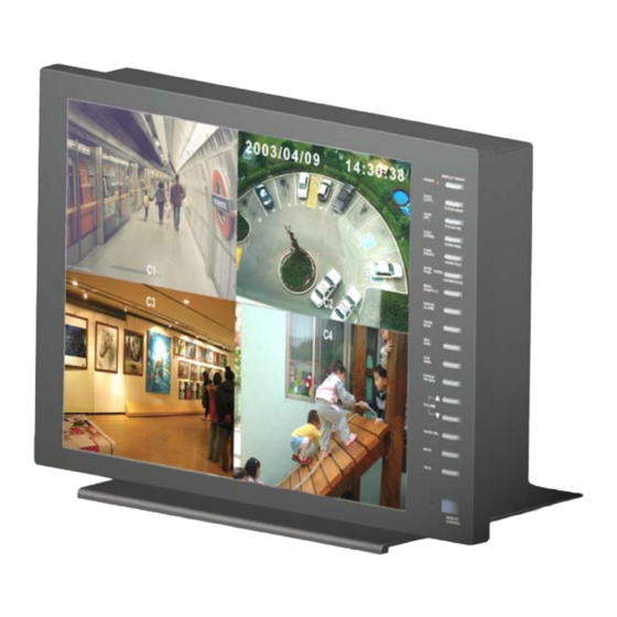
- Page 2 Thank you for purchasing the 17” Color TFT Quad Observation system. LOREX is committed to providing our customers with a high quality, reliable security product that customers have come to expect from us. This unique and innovative system displays a full, flat 17” viewing area making the system ideal for placement on any desk or counter top.
- Page 3 NOTE This equipment has been certified and found to comply with the limits regulated by FCC, EMC and LVD. Therefore, it is designed to provide reasonable protection against interference and will not cause interference with other appliance usage. However, it is imperative that user follows this manual's guidelines to avoid improper usage which may result in damage to the unit, electrical shock and fire hazard or injury.
-
Page 4: Table Of Contents
CONTENTS: 1. GENERAL PRECAUTIONS --------------------------------------------------------------------- 2. CAUTIONS AND FEATURES ------------------------------------------------------------------ 3. SYSTEM --------------------------------------------------------------------------------------------- 4. CONNECTING THE TFT STAND ------------------------------------------------------------- 5. MONITOR CONTROLS - FRONT PANEL -------------------------------------------------- 6. MAIN MENU CONTROL ------------------------------------------------------------------------ 7. PAN/TILT ZOOM ----------------------------------------------------------------------------------- 8. MONITOR CONTROLS - BACK PANEL ---------------------------------------------------- 9. -
Page 5: General Precautions
GENERAL PRECAUTIONS: Read Instructions Servicing All of the safety and operating instructions should Do not attempt to service this product yourself as be read and understood before the product is used. opening or removing covers may expose you to Retain Instructions voltage or other hazards. -
Page 6: Cautions And Features
CAUTIONS: 1. All the warnings and instructions of this manual should be followed 2. Remove the plug from the outlet before cleaning. Do not use liquid aerosol detergents. Use water damped cloth for cleaning 3. Do not use this unit in very humid and wet places 4. -
Page 7: System
SYSTEM INCLUDES: 1 - 4 – 1/4” CCD COLOR PIR 17” TFT COLOR QUAD MONITOR CAMERAS WITH METAL STAND AND 57 FT CABLE (4 CAMERAS INCLUDED WITH MODEL SG17TQ5544-A. 1 CAMERA INCLUDED WITH MODEL SG17TQ5541-A.) CONNECTING THE TFT STAND: Use the supplied screws to connect the stand for the TFT monitor to the base. Brackets and screws are also included for Rack Mounting applications. -
Page 8: Monitor Controls - Front Panel
CONTROL - FRONT PANEL: 1. Standby Switch - This switch will turn the monitor ON/OFF. DISPLAY ON / OFF POWER A red LED indicator light is ON when the monitor is in Standby mode. Press the button to turn the power ON. Allow ◄... - Page 9 3. Menu / (Pan/Tilt) - This button serves 2 functions: a) Menu – Press this button to enter the menu option screen. For more information on Menu mode, please refer to page 8. b) Pan/Tilt – This button activates the Pan/Tilt feature. For more information on the Pan/Tilt Zoom feature please refer to page 10.
- Page 10 8. PIP/POP - This button allows you to view the cameras in Picture-In-Picture or Picture-On- Picture setting. PIP allows you to view two locations simultaneously, one being the main channel, the other being viewed as a small image on the screen. Dual PIP can also be selected, which displays two small images on the main screen.
-
Page 11: Main Menu Control
MAIN MENU CONTROL Enter the Menu screen by pressing the Menu button. Scroll through the eight options by pressing the UP and DOWN buttons. To enter a sub-menu, press the Enter button where the highlighted scroll bar is located. To exit the Main Menu, scroll down to the Exit option and press Enter. - Page 12 4. Title Set – This submenu allows you to change the title of each camera location (up to 8 characters), or remove the titles from the on-screen display. DISPLAY: Selecting [Y] will enable the camera titles to appear in the on-screen display. Selecting [N] will remove all titles from appearing in the on-screen display.
-
Page 13: Pan/Tilt Zoom
7. System Set - This sub-menu allows you to configure various preferences on the system. KEY BUZZER: When set to [Y], the system will make a sound when a key is pressed on the remote control or on the main panel of the monitor. LOSS BUZZER: When set to [Y], the system will make a sound when a camera becomes disconnected. - Page 14 You will see a contracted screen with a blue border. Use the Arrow keys to sideways, and ENTER to select whether to MOVE, ZOOM, or FOCUS the camera. (note: Focusing is currently not available on Lorex Dome cameras). Enter Pan/Tilt Zoom mode by holding the PAN/TILT key on the monitor for 3 seconds, or press the Pan/Tilt button on the remote control;...
-
Page 15: Monitor Controls - Back Panel
MONITOR CONTROLS - BACK PANEL: 4 5 6 1. BNC Camera Inputs - Channel 1-4 camera inputs (for cameras with standard Video outputs) 2. 6 Pin DIN Camera Inputs - Channel 1-4 Camera inputs (for cameras with 6 pin DIN inputs) 3. -
Page 16: Side Panel And Rs232 Protocol
CONTROLS - SIDE PANEL: 1. Power - This switch controls power to the entire unit. Depress the side with the ‘I‘ to turn the power ON. Depress the ‘O‘ side to turn the unit OFF. -13-... -
Page 17: Remote Control
REMOTE CONTROL: Features of the Remote Control. For more details on specific remote control features, refer to the Monitor features FUNCTION DESCRIPTION Turns Power to unit On/Off. MODE Toggles to VGA IN viewing MODE MUTE Cuts off the sound from the camera. AUDIO SEL Selects the Audio channel in Quad mode ▲... -
Page 18: Standard Wired Camera
STANDARD WIRED CAMERA: Camera Lens – Delivers high quality image by using a 1/4” CCD Image Sensor Microphone – Picks up sound around the camera Camera Inputs – Connects cable to monitor PIR Sensor – Detects movement/motion Speaker – Delivers sound from the monitor to the camera Bracket –... -
Page 19: Monitor Connections
MONITOR CONNECTIONS: 1. Camera 1 Input Connect one end of the supplied 65ft cable to the first wired camera, the other end to camera Input 1 2. Camera 2 – 4 Inputs Connect optional additional cameras to the camera 2-4 inputs using either the DIN or BNC camera inputs VIDEO AUDIO... -
Page 20: Technical Specifications
TECHNICAL SPECIFICATIONS: MONITOR Picture Tube 17” Color TFT Resolution 720 x 480 Camera Capable Up to 4 Quad Speed 30 fps Camera Input 4 DIN / 4 BNC Alarm Inputs/Outputs 4 / 2 Input signal Composite 1 V p-p (75 ohm) Contrast ratio 300:1 Brightness ratio... -
Page 21: Optional Accessories
OPTIONAL ACCESSORIES The following accessories are available to add to your existing system. CABLE TIME LAPSE VCR NIGHTVISION Weatherproof Night vision Extends viewing length Used to record key events. accessory. Allows you to from Camera to monitor. Select From a 40 hour real see in the dark up to 35-40 Available In 65, 100 and time or 1280 Hour time lapse... -
Page 22: Appendix A - Connecting Monitor To Astandard Vcr
APPENDIX - A CONNECTING MONITOR TO A STANDARD VCR: PLEASE SEE THE DIAGRAM BELOW FOR CONNECTING YOUR VCR TO THE MONITOR. NOTE: Ensure the Standard VCR’s channel is set to A/V Mode in order to ensure reception. Consult your VCR’s Owners Manual to set the VCR to this setting. AC100-240V 50/60Hz VGA IN MONITOR OUT... -
Page 23: Appendix B - Connecting To A Slave Monitor
APPENDIX - B CONNECTING TO A SLAVE MONITOR: Connections to another monitor (e.g. Slave Monitor) can be made through “MONITOR OUT” As show in the diagram below. AC100-240V 50/60Hz VGA IN MONITOR OUT VCR OUT VCR IN RS-232 MONITOR -20-... -
Page 24: Appendix C - Typical Configuration
APPENDIX - C TYPICAL CONFIGURATION FOR COMPLETE SYSTEM: COMPUTER AC100-240V 50/60Hz VGA IN MONITOR OUT VCR OUT VCR IN RS-232 SENSOR CAMERA MONITOR -21-... -
Page 25: Appendix D - Connecting To A Lorex Time Lapse Vcr For Alarm Recording
APPENDIX - D CONNECTING TO A LOREX TIME LAPSE VCR FOR ALARM RECORDING AC100-240V 50/60Hz VGA IN MONITOR OUT VCR OUT VCR IN RS-232 -22-... -
Page 26: Appendix E - Connecting To A Lorex Single Channel Dvr
APPENDIX - E CONNECTING TO A SINGLE CHANNEL DIGITAL VIDEO RECORDER FOR ALARM RECORDING AC100-240V 50/60Hz VGA IN MONITOR OUT VCR OUT VCR IN NO 8 15 COM RS-232 14 A/I NC 7 R/S 6 13 A/R E/O 5 12 D/F S/O 4 11 RX2 10 TX2... -
Page 27: Appendix - Frack Mount Installation
APPENDIX - F RACK MOUNT INSTALLATION Brackets and screws for Rack Mounting applications are provided. -24-... -
Page 28: Care And Maintenance
CARE AND MAINTENANCE: Please follow the following instructions to ensure proper care and maintenance of this system Keep your monitor and camera dry. If it gets wet, wipe it dry immediately. Use and store your unit in normal temperature environment. Extreme temperatures can shorten the life of the electronic devices.
Need help?
Do you have a question about the SG17TQ5540 Series and is the answer not in the manual?
Questions and answers