Table of Contents
Advertisement
Quick Links
Advertisement
Table of Contents
Troubleshooting

Related Manuals for Aquasafe WSL25 Pro

Summary of Contents for Aquasafe WSL25 Pro
- Page 1 AquaSafe WSL25 Pro Water Safety Laboratory Instruction Manual...
- Page 2 Contents Section 1: Introduction Section 2: Kit Contents Section 3: Single Incubator Instructions Section 4: Membrane Filtration Instructions Section 5: HydroTest HT1000 Instructions Section 6: Multi-parameter Instructions...
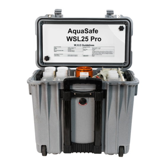
- Page 3 Section 1: Introduction The AquaSafe® WSL25 Pro is a fully portable field laboratory for the detection of microbiological and physico-chemical water quality parameters. The lab is housed in a waterproof wheeled carry case with telescopic handle and comprises the following: •...
- Page 4 Section 2: Kit Contents 10, 11 Under Accessories Box: 7, 8...
- Page 5 Main Case Components Item Description Sterilisable Work Surface AquaSafe® Single Incubator PetriLok® Cassette with cap and 25 Aluminium Petri Dishes Accessories Box HydroTest® HT1000 Bag HydroCheck® and Buffers Bag Silicone Grease Calibration Pack 5 Metre Sampling Cable with Carabiner IEC Mains Cable - UK...
- Page 6 HT1000 Bag Description HydroTest® HT1000 Digital Photometer Photometer 24mm Sample Vials Crushing Rod Lint-Free Wipes (10 Pack) HydroCheck® Bag Description HydroCheck® HC1000 Multi-Parameter Electrochemical Meter pH Probe for HydroCheck® EC Probe for HydroCheck® Thermal Probe for HydroCheck® pH 4.01 Buffer Solution pH 7.00 Buffer Solution EC 1413µS Calibration Solution Separate Box...
- Page 7 Section 3 AquaSafe Micro-biological Incubator Instruction Manual...
-
Page 8: Table Of Contents
Contents 1.0 Introduction ............................. 9 2.0 Incubator set-up ..........................10 2.1 Docking Station .......................... 10 2.2 Battery Removal ........................11 2.3 Battery Charging ........................11 2.4 Vehicle Power ..........................12 2.5 Fuse ............................12 3.0 Operating instructions ........................13 3.1 Incubator controls ........................13 3.2 Getting started ........................... -
Page 9: Introduction
1.0 Introduction The AquaSafe® Single Incubator is a portable incubator for the incubation of microbiological samples prepared using the membrane filtration method. The incubator is primarily designed to be used with the supplied 54mm x 3.5mm aluminium petri dishes which are suitable for 47mm membrane filter pads, but the incubator can also be used with 55mm pre-prepared plastic petri- dishes. -
Page 10: Incubator Set-Up
2.0 Incubator set-up The incubator is integrated into the waterproof carry case with a docking station which incorporates the rechargeable battery pack and power supply for the unit. An external charger is also supplied which is connected to the port on the rear of the case. On/Off Switch Charger Connection... -
Page 11: Battery Removal
2.2 Battery Removal It may be desired to remove the batteries or replace them at the end of their life. To replace or remove the batteries first ensure the switch on the rear of the carry case is in the off position then remove the screw on the left side of the docking station. -
Page 12: Vehicle Power
2.4 Vehicle Power The incubator is also supplied with a vehicle cigarette lighter cable. This cable can either be plugged into the socked on the rear of the carry case or into the incubator on the right side of the unit. -
Page 13: Operating Instructions
3.0 Operating instructions 3.1 Incubator controls LCD Display Petri-Lok® cassette The incubator has a power connection socket on the right hand side of the unit and three switches on the top which control all functions of the incubator. The incubator can be run from a power supply in the range 12 –... -
Page 14: Getting Started
3.2 Getting started Instructions for membrane filtration are covered in another section of the kit manual. The user should familiarise themselves fully with the set-up, control and calibration of the incubator prior to carrying out tests for the first time. If the incubator is connected to the docking station, turn on using the switch on the rear of the carry case. -
Page 15: Menu Sequence
3.3.1 Menu sequence Once the user has selected Restart or NewRun, pressing the left switch will step through the following sequence. Select Option Restart New Run Fig 1.0 20.9°C 24:00 20.9°C 24:00 10.5v <ADJ 10.5v Fig 1.1 Fig 1.8 20.9°C 24:00 20.9°C 24:00... -
Page 16: Start Screen (Figure 1.1)
3.3.2 Start Screen (Figure 1.1) Current Temperature Time Remaining 20.9°C 24:00 10.5v Battery Voltage Incubator Status Mode This screen shows the current status of the incubator. In the state shown the incubator is in idle mode and not running. -
Page 17: 37°C Program (Fig 1.2)
3.3.3 37°C Program (Fig 1.2) 20.9°C 24:00 ->37° 10.5v This mode is the pre-programmed default 37°C incubation cycle. In this mode the incubator will run an 18 hour incubation cycle at 37 °C. The timer can be altered to any setting between 0 and 24 hours. -
Page 18: 44°C Program (Fig1.3)
3.3.4 44°C Program (Fig1.3) 20.9°C 24:00 ->44° 10.5v This mode is the pre-programmed default 44°C incubation cycle. In this mode the incubator will run a 24 hour incubation cycle at 44°C. The timer can be altered to any setting between 0 and 24 hours. -
Page 19: User Defined Program (Fig 1.4)
3.3.5 User defined Program (Fig 1.4) 20.9°C 24:00 U->##° 10.5v This mode will run an incubation cycle at the user defined temperature for 24 hours. Adjusting the user defined temperature is described in section 3.3.8. The timer can be altered to any setting between 0 and 24 hours. -
Page 20: Incubation Cycle Time Setting (Fig 1.6)
3.3.7 Incubation cycle time setting (Fig 1.6) 20.9°C 24:00 <ADJ 10.5v In this mode the default cycle time can be changed from 24 hours to anywhere between 0 and 24 hours. Before adjusting the cycle time, reset the timer as described in section 3.3.6. To adjust the time press the middle switch. -
Page 21: Calibration (Fig 1.8)
3.3.9 Calibration (Fig 1.8) 20.9°C 24:00 Fig 3.1 <ADJ 10.5V In this mode the incubator is calibrated. To calibrate the unit the following equipment is required: Digital thermometer with 100mm x 4mm stainless steel probe (Included) Trace2o® Incubator calibration pack (Included) Petri-Lok®... -
Page 22: Care And Maintenance
The Petri-Lok® rack can be steam sterilised if required but it is not recommended to steam sterilise the top. The AquaSafe® carry case and integral docking station is waterproof when the lid is fully closed and the connector cap is fitted. When closed the case can be washed with a mild soap solution or rinsed with a hose. -
Page 23: Maintenance
4.3 Maintenance The wheels should be periodically cleaned. When dry add a drop of lubricating oil to the wheel axles to prevent seizing. All screws in the case are fitted with anti-vibration nuts or secured with adhesive. However, after transporting the case in a vehicle, it is suggested to check the integrity of the docking station and any screws to ensure no damage has occurred and all electrical connections are secure prior to use. -
Page 24: Incubator
47Kg 6.0 Guarantee and Assistance Trace2o® hope that the AquaSafe® incubator will give many years of trouble free operation, but in the event of a technical problem occurring the AquaSafe® incubator is covered by Trace2o® Ltd’s standard Guarantee terms and conditions available via email or via download from www.trace2o.com. - Page 25 Section 4 AquaSafe Membrane Filtration Instruction Manual...
- Page 26 Contents Contents SECTION 1: ASSEMBLY OF FILTRATION APPARATUS SECTION 2: PREPARING BACTERIOLOGICAL MEDIA IN A LABORATORY FACILITY SECTION 3: PREPARING BACTERIOLOGICAL MEDIA IN THE FIELD SECTION 4: SAMPLING SECTION 5: USE OF BACTERIOLOGICAL MEDIA SECTION 6: ASEPTIC PROCEDURES SECTION 7: PROCESSING SAMPLES FOR COLIFORM ANALYSIS SECTION 8: COUNTING COLIFORMS AND RECORDING THE RESULT SECTION 9: SELECTING THE OPTIMUM VOLUMES FOR MEMBRANE FILTRATION...
-
Page 27: Section 1: Assembly Of Filtration Apparatus
SECTION 1: ASSEMBLY OF FILTRATION APPARATUS 1. Hand Vacuum Pistol Pump 2. Filtrate Flask / Waste Beaker 3. Sampling Cup and cable 4. Graduated Aluminium Funnel 5. Membrane Support & Holder 6. Sealing Gaskets 7. Glass Sintered Disc (Membrane Support) - Page 28 Place one gasket within the recess of the support holder and press into place. Place the sintered disc, smooth side facing upwards, into the centre of the gasket. Push the other two gaskets into place around the sintered support disc. The graduated funnel screws clockwise into position.
-
Page 29: Section 2: Preparing Bacteriological Media In A Laboratory Facility
SECTION 2: PREPARING BACTERIOLOGICAL MEDIA IN A LABORATORY FACILITY Membrane Lauryl Sulfate Broth: For 50 tests, dissolve 7.62g of Membrane Lauryl Sulfate Broth (one sachet) in 100mL deionised water. The broth is supplied in a pre-weighed sterile sachet, with indicating silica gel that will turn from orange to green, to indicate moisture penetration. -
Page 30: Section 3: Preparing Bacteriological Media In The Field
SECTION 3: PREPARING BACTERIOLOGICAL MEDIA IN THE FIELD Membrane Lauryl Sulfate Broth: For 50 tests, dissolve 7.62g of Membrane Lauryl Sulfate Broth (one sachet) in 100mL deionised water. The broth is supplied in a pre-weighed sterile sachet, with indicating silica gel that will turn from orange to green, to indicate moisture penetration. -
Page 31: Section 4: Sampling
SECTION 4: SAMPLING Rivers and streams Take the sample as near as possible to the fastest flow – this will typically be found towards the centre of the body of water. Avoid taking samples from too close to the bank, where the water may be still and unrepresentative. - Page 32 Heat Disinfection of Tap This method is applicable for metal taps, but not for any plastic taps or taps with non- removable anti-splash devices. Turn off the tap fully, and flame the closed tap with a small Propane or Butane burner; cease flaming if/when any steam issues from the tap.
-
Page 33: Section 5: Use Of Bacteriological Media
SECTION 5: USE OF BACTERIOLOGICAL MEDIA If stored correctly, the dissolved media should remain stable for 6-8 weeks. However, if there are any signs of contamination e.g. yellowing, cloudiness etc., discard. Ideally, to reduce the possibility of contamination, use one bottle of media only for a 24 hour period, and use a fresh bottle on each subsequent day. -
Page 34: Section 6: Aseptic Procedures
SECTION 6: ASEPTIC PROCEDURES Aseptic procedures are of paramount importance during microbiological analysis, and extra care must be taken when outside the central laboratory, i.e. in the field. Everything must be kept clean and sterile, particularly on the following surfaces: Inner surface of the sampling cup Inner surface of the graduated filter funnel Filter membrane and absorbent pads... - Page 35 Pads are supplied sterile, in cartridges of 100. A sterile pad dispenser is supplied for depositing the pads into the petri-dishes. It is preferable to dispense pads at the central laboratory, prior to going to the sampling point; in this way, the dispenser may be kept attached to a pad cartridge and remain clean and sterile.
-
Page 36: Section 7: Processing Samples For Coliform Analysis
SECTION 7: PROCESSING SAMPLES FOR COLIFORM ANALYSIS All samples must be incubated within 6 hours of sampling. Dispense a sterile absorbent pad into a sterile petri dish, and saturate the pad with prepared broth Loosen the graduated filter funnel, and remove from the base support. Sterilise the forceps and allow to cool. - Page 37 Connect the hand vacuum pump to the filtration unit base and pump in a controlled fashion to suck the water sample through the membrane.
- Page 38 When all the water has been filtered, release the vacuum pump and use the sterile forceps to take the membrane from the filtration unit. Place the membrane on top of the pad, which has been previously saturated with the MLSB media.
-
Page 39: Section 8: Counting Coliforms And Recording The Result
SECTION 8: COUNTING COLIFORMS AND RECORDING THE RESULT Note the temperature that the incubator has been set for. Following incubation, switch off the power and remove the petri dishes from the incubator. Place the petri dishes on a flat, level surface. Remove the lids and count all the yellow colonies, irrespective of size. -
Page 40: Section 9: Selecting The Optimum Volumes For Membrane Filtration
SECTION 9: SELECTING THE OPTIMUM VOLUMES FOR MEMBRANE FILTRATION The optimum volume of sample is that which will allow the most accurate quantification of bacterial colonies. This is achieved when the number of faecal (thermotolerant) coliform colonies on the membrane following incubation is between 20 and 200 colonies. If there are fewer than 10 colonies, then there exists the possibility of statistical error. - Page 41 Section 5: HydroTest Photometer HT1000...
- Page 42 Contents Introduction ................. 5 Operation ................6 2.1.1 Set Up ................6 2.1.2 Saving Data – Important Information ......6 2.1.3 Replacement of Batteries ..........6 2.1.4 Instrument Diagram ............. 7 Overview of Function Keys ..........8 2.2.1 Overview ..............8 2.2.2 Displaying Time and Date ..........
- Page 43 2.4.7 Special Functions ............45 2.4.8 Instrument Basic Settings 2 ........47 2.4.9 Instrument Special Functions/Service ......48 Data Transfer ..............48 2.5.1 Data Printing .............. 48 2.5.2 Data Transfer to a Personal Computer ...... 48 Enclosure ................49 Unpacking ..............49 Technical Data ..............
-
Page 44: Introduction
1.0 Introduction The HT1000 is part of the HydroTest range of instruments based on optical measurement technology for the analysis of a range of chemical parameters in aqueous samples. The HT1000 is a photometric analyser using 6 individual selective wavelengths to measure the colour change produced by a reagent when reacted with the analyte of interest. -
Page 45: Operation
2.0 Operation 2.1.1 Set Up Before working with the photometer, it may be necessary to insert the batteries if supplied separately. See chapters 2.1.2 Saving Data – Important Information and 2.1.3 Replacement of Batteries. Before using the photometer, perform the following settings in the Mode-Menu. This is achieved by turning the device on and pressing the [MODE] key. -
Page 46: Instrument Diagram
2.1.4 Instrument Diagram (A) Screws (B) Battery Compartment Cover (C) Notch (D) Batteries – 4 x AA/LR6 (E) Seal Ring (F) Instrument Back CAUTION: To ensure that the instrument is waterproof: Seal ring (E) must be in position Battery compartment cover (B) must be fixed with the four screws... -
Page 47: Overview Of Function Keys
Overview of Function Keys 2.2.1 Overview Switching the photometer on or off Press shift key to achieve figures 0-9. Keep the shift key depressed and press desired figured key. E.g. [Shift] + [1] [1] Function 1 key: description in the text if key available Function 2 key: description in the text if key available Function 3 key: description in text if key available Displaying date and time / user countdown... -
Page 48: Displaying Time And Date
2.2.2 Displaying Time and Date Press [‘clock’] key. 19:30:22 2012-06-15 Display shows: After 15 seconds, the photo meter reverts to the previous display automatically, alternatively press [ESC] or [ ]. 2.2.3 User Countdown With this function the operator is able to define their own countdown. Press [‘clock’] key. -
Page 49: Automatic Switch Off
2.3.1 Automatic Switch Off The instrument switches off automatically after 20 minutes. This is indicated 30 seconds before by a beeper. Press any key to avoid the instrument switching off. As long as the instrument is working (for example countdown or printing) the automatic switch off is disabled. -
Page 50: Chemical Species Information
2.3.4 Chemical Species Information Pressing the [F2] key for a method in the method list gives the available chemical species and corresponding ranges. See Chapter 2.3.8 Changing Chemical Species Example: 320 Phosphate LR T Line 1: Method number, method name 0.05-4 mg/l PO Line 2: Range with chemical species 1 0.02-1.3 mg/l P... -
Page 51: Performing Tests
2.3.7 Performing Tests When zero calibration is complete, remove the vial from the sample chamber and perform the tests as described in the relevant application note. When the results have been displayed, options include: Storing and/or printing the results For some methods, changing between different chemical species Performing further analysis with the same zero Selecting a new method 2.3.8 Changing Chemical Species... -
Page 52: Storing Results
2.3.9 Storing Results Press [STORE] key while the test result is displayed. The display shows: Code-No.: _ _ _ _ _ _ We advise you to enter a numeric code (up to 6 digits). A code no. can contain references to the operator or the sampling location. e.g. -
Page 53: Performing Additional Measurements
2.3.11 Performing Additional Measurements To perform additional tests using the same method Press [TEST] key. The display shows: Zero accepted prepare Test press TEST Confirm with [TEST] key. Or press [ZERO] key to perform a new zero calibration. The display shows: prepare Zero press ZERO 2.3.12 Selecting a New Method... -
Page 54: Measuring Absorbance
2.3.13 Measuring Absorbance Range: - 2600 mAbs to + 2600 mAbs Method-No. Method Title mAbs 430 nm mAbs 530 nm mAbs 560 nm mAbs 580 nm mAbs 610 nm mAbs 660 nm Select the desired wavelength from the method list or by entering the corresponding method number directly. -
Page 55: Photometer Settings: Table Of Mode Functions
Photometer Settings: Table of Mode Functions Mode- Description Page Function Language Select Language Key-beep Switch the acoustic signal off/off to indicate key-pressing Clock Set date and time Countdown Switch countdown on/off to ensure reaction times Signal-beep Switch acoustic signal on/off to indicate end of reading Print Print all stored results... -
Page 56: Instrument Basic Settings 1
User Enter the data necessary to run a user concentr. concentration method User Enter the data necessary to run a user polynoms polynomial User m. clear Delete all data of a user polynomial or concentration method User m. print Print out all data stored with mode 64 and User m. - Page 57 Press [Shift] + [0] keys to switch the key beep off. Press [Shift] + [1] keys to switch the key beep on. Confirm with [ ] key. Note: In the case of methods with reaction periods, the acoustic signal still sounds during the last 10 seconds of the countdown even if the key beep is switched off.
- Page 58 Setting Date and Time Press [MODE], [Shift] + [1] [2] keys. Confirm with [ ] key. The display shows: < Clock > yy-mm-dd hh:mm The entry comprises two digits each for year, month day, minutes and _ _-_ _-_ _ _ _:_ _ seconds.
-
Page 59: Printing Of Stored Results
Signal Beep Performing a zero of a measurement takes 8 seconds. The photometer indicates the end of zeroing or measuring by a short beep. Press [MODE], [Shift] + [1] [4] keys. Confirm with [ ] key. The display shows: < Signal-beep > ON: 1, OFF: 0 Press [Shift] + [0] keys to switch the signal beep off. - Page 60 Printing Results of a Selected Time Period Press [MODE], [Shift] + [2] [1] keys. Confirm with [ ] key. The display shows: < Print > sorted: date Enter year, month and day for the first day of the required period e.g. 14 from yy-mm-dd May 2009 = [Shift] + [0] [9] [0] [5] [1] [4] _ _-_ _-_ _...
- Page 61 Confirm with [ ] key. The display shows: Test No.: < Print > sorted: Code No. Enter numeric code number (up to 6 places) for the first required Code No. to _ _ _ _ _ _ e.g. [Shift] + [1] [0] Confirm with [ ] key.
-
Page 62: Recall/Delete Stored Results
Printing Parameter Press [MODE], [Shift] + [2] [9] keys. Confirm with [ ] key. The display shows: < Printing params. > 2: Baud rate cancel: ESC Press [Shift] + [2] keys to select “Baud rate”. < Baud rate > The display shows: is: 9600 select ↑↓: save:... - Page 63 End with [ESC] key. Press arrow key [ ] to display the next test result. Press arrow key [ ] to display the previous test result. If there are no test results in the memory, the display shows: No data Recall Results of a Selected Time Period Press [MODE], [Shift] + [3] [1] keys.
- Page 64 Recall Results of a Selected Code No. Range Press [MODE], [Shift] + [3] [2] keys. Confirm with [ ] key. The display shows: < Storage > Enter numeric code number (up to 6 places) for the first required Code No. sorted: Code-No.
- Page 65 Recall Results of a Selected Method Press [MODE], [Shift] + [3] [3] keys. Confirm with [ ] key. < Storage > The display shows: >> 20 Acid demand T 35 Alkalinity-p T Select the required method from the displayed list or enter the method number directly.
-
Page 66: Calibration
Delete Stored Results Press [MODE], [Shift] + [3] [4] keys. Confirm with [ ] key. < Delete data > The display shows: Delete all data? Select the required method from the displayed list or enter the method YES: 1 NO: 0 number directly. - Page 67 4. Remove vial from the sample chamber. 5. Pipette 100 ml of water free of calcium to an appropriate beaker (see notes 2 & 3 below). 6. Add 10 CALCIO H No. 1 tablets straight from the foil to the 100 ml of water, crush the tablets using a clean stirring road and dissolve the tablets completely.
- Page 68 Press [Shift] + [2] keys. The display shows: < Calibration > 191 Ca-hardness 2 T Reset? YES: 1 NO: 0 Press [Shift] + [0] keys to keep the method blank. Press [Shift] + [1] keys to erase the method blank and set the value back to factory calibration.
- Page 69 10. Add exactly 2 ml SPADNS reagent solution to the fluoride standard. Caution: vial is filled up to the top! 11. Place the vial in the sample chamber, making sure that the triangular marks on the vial and instrument are aligned. 12.
- Page 70 User Calibration If a test method is user calibrated, the method name is displayed inverse. Procedure: Prepare a standard of known concentration and use this standard instead of the sample according to the test procedure. It is recommended to use well known standard which hare formulated according to DIN EN, ASTM or other international norms or to use the certified standards which are commercially available.
- Page 71 210 H Calibration with basic test 100 chlorine free No. Method Recommended range for user calibration 190 Hardness, 100-200 mg/l CaCO Calcium 191 Hardness, 100-200 mg/l CaCO Calcium 2 200 Hardness-total 15-25 mg/l CaCO 215 Iodine Calibration with basic test 100 chlorine free 220 Iron 0.3-0.7 mg/l Fe...
- Page 72 Store User Calibration Perform the required method as described in the manual using a standard of known concentration instead of the water sample. 100 Chlorine T 0.02-6 mg/l Cl2 0.90 mg/l free Cl2 If the test result is displayed, press [MODE], [Shift] + [4] [5] keys.
-
Page 73: Lab Function
Instead of zeroing the instrument, press [MODE], [Shift] + [4] [6]. Confirm with [ ] key. The display shows: <User calibration> Chlorine T 0.02-6 mg/l Cl2 1.00 mg/l free Cl2 Clear user calibration? YES: 1, NO: 0 Press [Shift] + [1] keys to delete user calibration. Press [Shift] + [0] keys to keep the valid user calibration. - Page 74 <Profi-Mode> Switched on Confirm with [ ] key. Note: Storage of test results is possible. When results are stored, the display also shows ‘Profi- Mode’. The selected settings are kept by the photometer even when it is switched off. To change the photometer settings, a new setting is required.
-
Page 75: User Options
2.4.6 User Options User Method List After switching on the instrument, a scroll list of all available methods is automatically shown in the display. To shorten this list according to the requirements of the user, it is possible to create a user defined scroll list. - Page 76 User Method List, Switch All Methods On This mode function activates all methods. After switching on the instrument a scroll list of all available methods is automatically shown in the display. Press [MODE], [Shift] + [6] [1] keys. Confirm with [ ] key. The display shows: <Mlist all on>...
- Page 77 Entering a User Concentration Press [MODE], [Shift] + [6] [4] keys. Confirm with [ ] key. ENTRY PROCEDURE The display shows: <User concentr.> choose no.: _ _ _ (850-859) Enter a method number in the range from 850 to 859 e.g.
- Page 78 The display shows: <User concentr.> Press the appropriate numerical key to select the required resolution choose resolution e.g. [Shift] + [3] for 0.01 1: 1 2: 0.1 Note: Please enter the required resolution according to the instrument pre- 3: 0.01 sets: Range Max.
- Page 79 Prepare the first standard and press [TEST] key. The display shows the input value and measured absorption value. <User concentr.> S1: 0.05 mg/l mAbs: 12 Confirm with [ ] key. The display shows: <User concentr.> S1 accepted S2: + _____ │...
- Page 80 You might want to use mode 67 to transfer all concentration data to a PC. User Polynomials It is possible to enter and store up to 25 User Polynomials. The programme allows the user to apply a Polynomial up to the 5 degree: y = A + Bx + Cx + Dx...
- Page 81 Enter data of the coefficient A including decimal point e.g. [Shift] + [1] [.][3][2] Press [F1] key to reset numerical input. Confirm with [ ] key. The display shows: <User polynoms.> A: 1.32___ E+____ Press arrow key [ ] or [ ] to change between plus and minus sign. Enter the exponent of the coefficient A e.g.
- Page 82 The display shows: <User polynoms.> Press the appropriate numerical key to select the required resolution choose resolution e.g. [Shift] + [3] for 0.01 1: 1 2: 0.1 Note: Please enter the required resolution according to the instrument pre- 3: 0.01 sets: Range Max.
- Page 83 Press [Shift] + [1] keys to delete the selected used method. Press [Shift] + [0] keys to keep the valid user method. The instrument goes back to mode menu automatically. Print Data of User Methods (Polynomials & Concentration) With this mode function, all data (e.g. wavelength, unit …) of stored user polynomials and concentration methods can be printed out or transferred with HyperTerminal to a PC.
-
Page 84: Special Functions
2.4.7 Special Functions Langelier Saturation Index (Water Balance) For calculation, the following tests are required: - pH-value - Temperature - Calcium hardness - Total alkalinity - TDS (Total Dissolved Solids) Run each test separately and note the results. Calculate the Langelier Saturation index as described: Calculation of the Langelier Saturation Index With mode 71 (see below), it is possible to select between degree Celsius and degrees Fahrenheit. - Page 85 The display shows the Langelier Saturation Index. <Langelier> Langelier saturation index 0.00 Press [ ] key to start new calculation. Return to mode menu by pressing [ESC] key. Operating error: Examples: Values out of defined range: The entered value is too high. CH <= 1000 mg/l CaCO The entered value is too low.
-
Page 86: Instrument Basic Settings 2
2.4.8 Instrument Basic Settings 2 Adjusting Display Contrast Press [MODE], [Shift] + [8] [0] keys. Confirm with [ ] key. The display shows: <LCD contrast> 1 ↑ 1 ↓ Store Test Press arrow key [ ] to increase the contrast of the LCD display by one unit. 0…254: 180 Press arrow key [ ] to decrease the contrast of the LCD display by one unit. -
Page 87: Instrument Special Functions/Service
2.4.9 Instrument Special Functions/Service Photometer Information Press [MODE], [Shift] + [9] [1] keys. Confirm with [ ] key. This method informs you about the current software version, about the <System-Info> number of performed tests and free memory capacity. Software: V2012.001.1.001.002 more: ↓, cancel: ESC Press arrow key [ ] to display the number of performed test and free memory capacity. -
Page 88: Enclosure
Enclosure Unpacking Carefully inspect all items to ensure that every part of the list below is present and no visible damage has occurred during shipment. If there is any damage, or something is missing, please contact your local distributor immediately. Technical Data Display Graphic display with backlight... -
Page 89: Abbreviations
30 seconds acoustic signal before switch Dimensions Approx. 210 x 95 x 45 mm (unit) Approx. 395 x 295 x 106 mm (case) Weight (unit) Approx. 450 g Working Condition 5-40 °C at max. 30-90 % relative humidity (without condensation) Language Options English, German, French, Spanish, Italian, Portuguese, Polish;... - Page 90 Total Dissolved Solids Low Range Medium Range High Range Liquid Reagent Powder (reagent) Powder Pack Tablet Tube Test DEHA N, N-Diethylhydroxylamine Diethyl-p-phenylenediamine DTNB Ellman’s reagent 1-(2-Pyridylazo)-2-napthol PMAB Paradimethylaminobenzaldehyde PPST 3-(2-Pyridyl)-5,6-bis(4-phenylsulfonic acid)1,2,4-triazine TPTZ 2,4,6-Tri-92-Pyridyl)-1,3,5-triazine...
-
Page 91: Troubleshooting
Troubleshooting 3.4.1 Operating Messages in the Display/Error Display Display Possible Causes Elimination Overrange Reading is exceeding If possible, dilute sample or use the range other measuring range Water sample is too Filter water sample cloudy Too much light on the Seal the cap photo cell Repeat measurement with seal... - Page 92 E40 User If the display shows Perform the test with a calibration not overrange/underrange standard of higher/lower possible for a test result, a user concentration calibration is not possible Zero not Light absorption is too Refer to Chapter 2.3.5 accepted great or too low Performing Zero Clean sample chamber...
-
Page 93: General
3.4.2 General Finding Possible Causes Elimination Test result Chemical species not as Press arrow keys to select the deviated from required required chemical species the expected Profi-Mode is switched Switch Profi-Mode off with differentiation mode 50 e.g. for the chlorine test there is no selection between... - Page 94 Trace2o Ltd Technology Centre Wagtech Court Station Road Thatcham, Berkshire RG19 4HZ Tel: +44 (0)1635 566772 Fax: +44 (0)1635 873509 sales@trace2o.com www.trace2o.com...
- Page 95 ® HT1000 APPLICATION NOTE T2O-AN-P60 AMMONIA (P60) METHOD The following application note explains the procedure for the detection of Ammonia (P60) using the HT1000 Photometer. Equipment: • HT1000 Photometer • 10ml vial • Stirring rod • HT9 Ammonia No. 1 tablet •...
- Page 96 Blank analysis: • Ensure that the 10ml vial is clean. • Fill the vial with 10ml of the water sample. • Fit the cap and tighten. • Place the vial in the sample chamber, making sure that the arrow marks on the instrument and vial are aligned.
- Page 97 • The Lower LOD is 0.02 mg/l (20ppb), upper LOD is 1 mg/l (1000ppb). • Tolerance: ± 0.005mg/l. Notes • For best results, rinse vials thoroughly between with deionised water. Ensure that the outside of the vials are clean, dry and free from fingerprints. Always handle vials by the lid where possible.
- Page 98 ® HT1000 APPLICATION NOTE T2O-AN-P100 CHLORINE FREE & TOTAL (P100) METHOD The following application note explains the procedure for the detection of Free and Total Chlorine (P100) using the HT1000 Photometer. Equipment: • HT1000 Photometer • 10ml vial • Stirring rod •...
- Page 99 • Depress the cursor keys until the double arrow (>>) is adjacent to the required test (diff/free/total) and press enter. Blank analysis: • Ensure that the 10ml vial is clean. • Fill the vial with 10ml of the water sample. •...
- Page 100 • Wait for a few seconds until the result is displayed in mg/l free Chlorine. Sample preparation (Total Chlorine): • Add one HT15 DPD No.1 tablet and one HT16 DPD No. 3 tablet straight from the foil to the water sample. •...
- Page 101 • Remove the vial from the sample chamber. • Add one HT16 DPD No.3 tablet straight from the foil to the water sample. • Crush the tablet using a clean stirring rod, until no large pieces are visible. • Close the vial tightly with the cap and swirl several times until the tablet is dissolved. •...
- Page 102 ® HT1000 APPLICATION NOTE T2O-AN-P260 NITRATE (P260) METHOD The following application note explains the procedure for the detection of Nitrate (P260) using the HT1000 Photometer. Equipment: • HT1000 Photometer • Nitrate test tube • Nitrate test powder • Nitrate Test tablet •...
- Page 103 Blank analysis: • Ensure that the 10ml vial is clean. • Fill the vial with 10ml of the water sample. • Fit the cap and tighten. • Place the vial in the sample chamber, making sure that the arrow marks on the instrument and vial are aligned.
- Page 104 • Place the vial in the sample chamber, making sure that the marks on the instrument and vial are aligned. • Press the Test key • Wait for a reaction period of 10 minutes • After the reaction period, the measurement starts and the result is displayed in mg/l Nitrate LOD/Tolerance •...
- Page 105 ® HT1000 APPLICATION NOTE T2O-AN-P270 NITRITE (P270) METHOD The following application note explains the procedure for the detection of Nitrite (P270) using the HT1000 Photometer. Equipment: • HT1000 Photometer • 10ml vial • Stirring rod • Nitrite LR tablet Safety: •...
- Page 106 Blank analysis: • Ensure that the 10ml vial is clean. • Fill the vial with 10ml of the water sample. • Fit the cap and tighten. • Place the vial in the sample chamber, making sure that the arrow marks on the instrument and vial are aligned.
- Page 107 • The Lower LOD is 0.01 mg/l (10ppb), upper LOD is 0.5 mg/l (500ppb). • Tolerance: ± 0.005mg/l. Notes • For best results, rinse vials thoroughly between with deionised water. Ensure that the outside of the vials are clean, dry and free from fingerprints. Always handle vials by the lid where possible.
- Page 108 Section 6: HydroCheck® HC1000 Multi-Parameter Electrochemical Water Tester Instruction Manual...
- Page 109 Contents 1.1 Introduction ................72 1.2 Unpacking the Meter ..............72 1.3 List of Accessories ..............72 2.1 Display ..................72 2.2 Keypad ..................73 2.3 Connectors ................74 2.4 Connecting the Sensors ............75 2.5 Inserting/Replacing the Batteries ..........76 2.6 Refilling Electrolyte Solution for DO Probe .......
- Page 110 13.1 Appendix 1: How to calculate the temperature coefficient ..109 13.2 Appendix 2: How to calculate the TDS conversion factor ..109 13.3 Appendix 3: Pressure vs Altitude Table ........ 111 14.1 Warranty ................112...
-
Page 111: Introduction
1.1 Introduction Thank you for selecting the Trace2o® HydroCheck HC1000 portable multiparameter water quality meter. This manual provides instructions to guide the user in normal operation, diagnostics and maintenance of the instrument. Please read the instructions carefully before use. 1.2 Unpacking the Meter Before unpacking, ensure that the current work environment meet following conditions. -
Page 112: Keypad
INDEX: Measurement mode Battery indicator Calibration Stable indicator mode Setup mode Hold indicator Memory mode Calibration Due Reminder Electrode Automatic Temperature slope Compensation: indicator 2.2 Keypad The Trace2o® HydroCheck® HC1000 has a tactile membrane keypad. Words and symbols describe functions of each key. The direction keys are multi-function left/right and up/down keys. -
Page 113: Connectors
• Press to enter the calibration mode. • Press and hold to enter the setup menu. • Press to store current measured value. • Press in setup mode to scroll up through menu. m+ / ▲ • Press in temperature setting mode to increase the setting value. •... -
Page 114: Connecting The Sensors
2.4 Connecting the Sensors Take out the sensor from the carrying case. Ensure the connectors are clean and dry before connecting. pH ELECTRODE • Insert the S7 connector on the pH electrode into corresponding connector on the instrument. Once pushed firmly into place, twist to ensure water tightness. CONDUCTIVITY ELECTRODE •... -
Page 115: Inserting/Replacing The Batteries
DISSOLVED OXYGEN ELECTRODE • Insert the 6-pin connector on the temperature probe into the corresponding connector on the instrument, ensuring that the lugs are aligned. Once pushed firmly into place, tighten the waterproof locking collar. • Once connected, DO NOT pull on the cables. 2.5 Inserting/Replacing the Batteries The HC1000 is supplied pre-installed with the requisite battery. -
Page 116: Refilling Electrolyte Solution For Do Probe
3. Note the polarity and attach the snap connector to the appropriate terminals on the new battery. 4. Ensure that the white waterproofing seal is correctly located, and replace the battery cover. When batteries are depleted, the meter allows you to use the USB cable connected to computer as a temporarily power supply. -
Page 117: Power On/Off
Prior to Use Remove the protective cap from the bottom of the sensor. 3.1 Power On/Off • To turn the meter on, press the ON/OFF key. • To turn the meter off, press and hold the ON/OFF key for 3 seconds, •... -
Page 118: Conductivity/Tds/Resistivity Measurement
3.4 Conductivity/TDS/Resistivity Measurement 1. Press the MODE key until the display shows the (Conductivity) or (TDS) or (Resistivity) indicator. 2. Rinse the conductivity electrode thoroughly with distilled water. 3. Immerse the electrode in the sample solution, and stir the solution gently. 4. -
Page 119: Hold Function
1. Press MODE key until the meter shows indicator. 2. Connecting the dissolved oxygen probe to meter, wait for 15 minutes to polarise the sensor. 3. If necessary, to set the atmospheric pressure and salinity coefficient in the setup menu (Refer to “SETUP MENU”... - Page 120 Enter ..…..….Page number 3. Press the ▼ key, the meter shows the date and time of the reading (Format: mm-dd, hh- mm). 4. Press the ▼ key again, the display shows the stored data. 5. After viewing the memory, press the ON/OFF key to return to measurement mode.
-
Page 121: Setup Menu
4.1 Setup Menu When in setup mode, the HC1000 displays an integrated setup menu that allows you customise to the operation of the meter to meet your measurement requirements. In the different modes, the meter will show the corresponding options. For general options, the change will be applied to all modes. - Page 122 CONDUCTIVITY/TDS/SALINITY/RESISTIVITY MODES: DESCRIPTIO OPTIO DESCRIPTIO DEFAU DISPLAY K=0.1 Select the cell ● constant of conductivity K=10 electrode. User-Defined Select the Setting Range: temperature 0.0 to 2.10 coefficient of 10.0%/ sample. Select the 1 point ● number of 2 points calibration points to use 3 points when...
- Page 123 DISSOLVED OXYGEN MODE: DESCRIPTIO OPTIO DESCRIPTIO DEFAU DISPLAY Select the 1 point ● number of calibration 2 points points. Select the Setting Range: default atmospheric 450 to pressure 850mmHg coefficient. Select the salinity Setting Range: coefficient of 0.0 to 50.0ppt sample solution.
- Page 124 GENERAL OPTIONS: DESCRIPTIO OPTIO DESCRIPTIO DEFAU DISPLAY Sets the stability criteria ● measurement. When the “LO” option is enabled, measuring value will stabilize quickly, but reading is less accurate. High When the “HI” option is enabled, measuring value will stabilize slowly, but improves accuracy.
- Page 125 the meter will automatically show indicator. Sets the date and time of the meter. Enable Clear all stored data. Disable ● Reset function allows user to Enable restore the meter to factory default settings. When this function is used, all Disable ●...
-
Page 126: Adjusting The Settings
4.2 Adjusting the settings: 1. If necessary, press MODE key until the display shows corresponding mode indicator (e.g., pH mode). 2. Press and hold the CAL key for 3 seconds, the meter enters setup mode, the display shows adjustable setting, and parameter number. …………Setting …………Parameter number 3. -
Page 127: Temperature Compensation
1. Press and hold the CAL key for 3 seconds to enter setup mode. 2. Press ▲ or ▼ key until the display shows the “DATE” option. 3. Press ENTER key to confirm, the meter shows the currently programmed year. …………Year Enter 4. -
Page 128: Manual Temperature Compensation
4.7 Manual Temperature Compensation: 4.7.1. DO NOT connect the temperature probe to meter. 4.7.2. Press and hold the MODE key for 3 seconds to enter temperature setting mode. 4.7.3. Press ▲ or ▼ key to set the temperature of the sample. 4.7.4. -
Page 129: Multi-Point Calibration
5.2.5 Press ENTER key, “Calibration” indicator begins flashing. Wait for the measured value to stabilize; the display shows “END”. The meter returns to measurement mode automatically. Æ 5.3 Multi-Point Calibration: 5.3.1 Make sure that you have selected between 2 and to 5 point calibration in the setup menu. -
Page 130: Ph Calibration With User-Defined Buffers
5.4 pH Calibration with User-Defined Buffers: 5.4.1 Ensure that the “USER” option is selected in the setup menu. N.B. Custom buffer solution values should be at least 1 pH unit apart. 5.4.2 Rinse the pH electrode with distilled water. Immerse the electrode in the custom buffer solution. -
Page 131: Ph Calibration Report
5.5 pH Calibration Report The meter allows checking of the calibration data of the pH electrode for diagnostic purposes. 5.5.1. Press the mR key in the pH measurement mode, the display shows “LOC/P-01”. 5.5.2. Press ▲ or ▼ key until the display shows “ELE/P-02” (Electrode Diagnosis). 5.5.3. - Page 132 2. Rinse the ORP electrode with distilled water. Immerse the electrode in the calibration solution. Stir the solution gently. 3. Press CAL key, the meter shows the current measured value. 4. Press ▲ or ▼ key to set the displayed value, press ENTER key to confirm. The “Calibration”...
-
Page 133: Orp Calibration Report
6.2 ORP Calibration Report The meter allows checking the mV offset of the ORP electrode for diagnostic purposes. 1. Press the mR key in the ORP measurement mode, the display shows “LOC/P-01”. 2. Press ▲ or ▼ key until the meter shows “ELE/P-02” (Electrode Diagnosis). 3. - Page 134 200~2000µS/cm 700~1700µS/cm 1413µS/cm 2~20mS/cm 7~17mS/cm 12.88mS/cm 20~200mS/cm 70~170mS/cm 111.8mS/cm...
-
Page 135: Single Point Calibration
7.2 Single Point Calibration: 7.2.1 Press the MODE key until the meter shows the indicator. 7.2.2 Rinse the conductivity electrode with distilled water, then rinse with a small amount of calibration solution. 7.2.3 Press the CAL key; the meter enters the calibration mode. 7.2.4 Immerse the conductivity electrode in the calibration solution. - Page 136 7.3.3 Rinse the conductivity electrode with distilled water. Immerse the electrode in the next calibration solution, the meter automatically shows the currently detected calibration standard (e.g., 12.88mS/cm). 7.3.4 Press ENTER key to confirm, “Calibration” indicator begins flashing. Enter 7.3.5 Wait for the measured value to stabilise, the display shows “CAL3”. The meter prompts you to continue with third point calibration.
-
Page 137: Manual Calibration
7.4 Manual Calibration: The HC1000 offers a quick manual calibration mode, allowing the user to easily calibrate the meter. 7.4.1 Record the cell constant value, which is clearly marked on a label attached to the electrode (e.g., K=1.08). 7.4.2 Ensure the Cal indicator is showing, and press and hold the CAL key for 3 seconds to enter setup menu, the display shows “CELL”... -
Page 138: Conductivity Calibration Report
• To exit calibration, press ON/OFF key; the meter will return to measurement mode immediately. • Performing the conductivity calibration will simultaneously calibrate the corresponding TDS, salinity and resistivity value. 7.5 Conductivity Calibration Report The meter allows checking of the calibration factor of the conductivity electrode for diagnostic purposes. - Page 139 8.2.2 Make sure that 1 point calibration is selected in the setup menu. 8.2.3 Press CAL key; the meter enters calibration mode, the display shows “100%/CAL1”. 8.2.4 Hold the dissolved oxygen probe in the air, press ENTER key to confirm. Wait for the measured value to stabilise, the display shows “END”.
-
Page 140: Point Calibration
8.3 2 Point Calibration: 8.3.1 Ensure that 2 point calibration is selected in the setup menu. 8.3.2 Press CAL key, the meter shows “100/CAL1”. 8.3.3 Press ▲ or ▼ key until the display shows “0/CAL1”. 8.3.4 Immerse the dissolved oxygen probe into the saturated anhydrous sodium sulfite solution (zero oxygen solution). -
Page 142: Do Calibration In Mg/L Or Ppm Mode
9.1 DO Calibration in mg/L or ppm Mode 9.1.1 Press MODE key until the meter shows indicator and measurement unit “mg/L” or “ppm”. 9.1.2 Ensure that 1 point calibration is selected in the setup menu. 9.1.3 If necessary, set the salinity and atmospheric pressure coefficient in the setup menu (Refer to Setup Menu section). -
Page 143: Point Calibration
9.2 2 Point Calibration: 9.2.1 Make sure that you have selected 2 points calibration in the setup menu. 9.2.2 Press CAL key, the meter shows “8.25mg/L/CAL1” (@25 9.2.3 Press ▲ or ▼ key until the display shows “0.00mg/L/CAL1”. 9.2.4 Immerse the dissolved oxygen probe into the saturated anhydrous sodium sulfite solution (zero oxygen solution). -
Page 144: Temperature Calibration
10.1 Temperature Calibration When automatic temperature compensation is enabled, the meter will need to be calibrated if the temperature reading displayed differs from that of an accurate thermometer. 10.1.1. Press and hold the MODE key for 3 seconds to enter temperature calibration mode, the display shows current temperature reading. -
Page 145: Ph Electrode Care And Maintenance
11.1 pH Electrode Care and Maintenance The pH electrode is especially susceptible to dirt and contamination. Regular cleaning is necessary depending on the extent and condition of use. AFTER MEASURING: Rinse the pH electrode in distilled water, and store the electrode in a suitable electrode storage solution. -
Page 146: Conductivity Electrode Care And Maintenance
Oil and Grease Films: • Wash the electrode gently with detergent and water. • Immerse the electrode in electrode storage solution for at least 30 minutes. 11.3 Conductivity Electrode Care and Maintenance • Ensure that the conductivity electrode is thoroughly washed with distilled water after each use. - Page 147 Zero oxygen solution Replace the calibration is contaminated solution...
-
Page 148: Appendix 1: How To Calculate The Temperature Coefficient
13.1 Appendix 1: How to calculate the temperature coefficient To determine the temperature coefficient of sample solution, use the following formula: ×100% -25)-C -25) Where: =Temperature coefficient =Conductivity at Temperature A =Conductivity at Temperature B =Temperature A =Temperature B 1. Press and hold the MODE key for 3 seconds to enter temperature setting mode. 2. - Page 149 Actual Conductivity: the meter measured conductivity value. For example: Dissolve 64 grams of potassium chloride reagent in 1L distilled water. If its conductivity value is 100mS/cm, then TDS conversion factor is 0.64.
-
Page 150: Appendix 3: Pressure Vs Altitude Table
13.3 Appendix 3: Pressure vs Altitude Table ALTITUDE (m) mmHg 101.3 100.1 98.8 97.6 96.4 95.2 94.0 92.8 91.7 90.5 1000 89.4 1100 88.3 1200 87.2 1300 86.1 1400 85.0 1500 84.0 1600 82.9 1700 81.9 1800 80.9 1900 79.9 2000 78.9... -
Page 151: Warranty
14.1 Warranty Trace2o hopes that the HydroCheck HC1000 will give many years of trouble-free operation, but in the event of a technical problem occurring the instrument is covered by the Trace2o Ltd standard warranty terms and conditions available via email or via download from www.trace2o.com. - Page 152 NOTES...
- Page 153 Trace2o® Limited The Technology Centre Wagtech Court Station Road Thatcham, Berkshire, RG19 4HZ Tel.: +44 (0)1635 566772 Fax: +44 (0)1635 873509 sales@Trace2o.com www.Trace2o.com...
Need help?
Do you have a question about the WSL25 Pro and is the answer not in the manual?
Questions and answers