Table of Contents
Advertisement
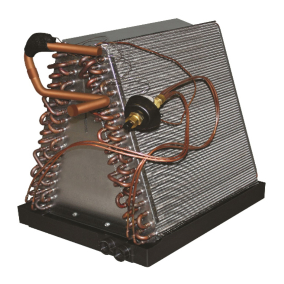
Split System Indoor Coils
Installation Instructions
Read the installation instructions supplied with the furnace/air
handler and observe all safety requirements outlined in the in-
structions and/or furnace/air handler markings before proceeding
with the installation of the coil.
These instructions are primarily intended to assist qualifi ed individuals
experienced in the proper installation of this appliance. Some local and
national codes require licensed installation/service personnel for this
type of equipment. Read all instructions carefully before starting the
installation.
CAUTION:
Advertisement
Table of Contents

Related Manuals for Nordyne C5DA


Summary of Contents for Nordyne C5DA
- Page 1 Split System Indoor Coils Installation Instructions CAUTION: Read the installation instructions supplied with the furnace/air handler and observe all safety requirements outlined in the in- structions and/or furnace/air handler markings before proceeding with the installation of the coil. These instructions are primarily intended to assist qualifi ed individuals experienced in the proper installation of this appliance.
-
Page 2: Table Of Contents
Table of Contents 1. General Information ....................... 3 2. Coil Specifi cations ......................... 3 3. Coil Installation ........................4 • Upfl ow Furnace/Air Handler • Downfl ow Electric Furnace • Downfl ow Electric Furnace/Air Handler with Integral Coil Cabinet or Optional Coil Cabinet 4. -
Page 3: General Information
Refer to Coil Specifi cations for recommended CFM and allow for pressure drop across the coil and fi lters. 2. COIL SPECIFICATIONS C5DA Nominal (2) Capacity BTUH 24,000 30,000 36,000 36,000 42,000 42,000 48,000 48,000 48,000 60,000 Nominal Airfl... -
Page 4: Coil Installation
3. COIL INSTALLATION WARNING: Electric furnaces may be connected to more than one supply circuit. Upfl ow Furnace: Disconnect all electrical power to the furnace. Install the coil in the coil cabinet and level it as needed to allow proper condensate drainage or make a plenum to enclose the coil or drop the duct directly over it. -
Page 5: Verify Pressurization
TABS OFFSET SMALL PLATE SMALL PLATE LARGE MOUNTING PLATE LARGE HOLES (2) TABS PLATE MOUNTING HOLE Figure 4. Close-Off Plates for Opening at Figure 3. Bottom Close-Off Plates Top of Furnace Slide the close-off plates around the re- frigerant lines and install with the dart clips provided. -
Page 6: Refrigerant Line Connections
5. REFRIGERANT LINE CONNECTIONS WARNING: NITROGEN HEALTH FLAMMABILITY REACTIVITY 0 Minimal Hazard 1 Slight Hazard This coil is pressurized with Nitrogen. Avoid direct face exposure or contact Figure 7. Downfl ow Furnace with Coil with valve when gas is escaping. Al- Cabinet ways ensure adequate ventilation is present during the depressurization... -
Page 7: Completing The Installation
Line Connections: 11. Cut the line set tubing to the proper length. Be sure that the tubing has been sized in accordance with the outdoor unit specifi cations. 12. Inspect both refrigerant lines. The ends of the lines must be round, clean, and free of any burrs. -
Page 8: Refrigerant Charging
lines and drain line where required. Reinstall 7. MAINTENANCE AND SERVICE all inner and outer panels of the furnace/air To ensure optimum system performance and handler that were previously removed to install to minimize the possibility of equipment failure, the indoor coil. the following periodic maintenance should be performed on the coil: Refrigerant Charging —...
Need help?
Do you have a question about the C5DA and is the answer not in the manual?
Questions and answers