Table of Contents
Advertisement
Quick Links
Setting instructions and
Setting instructions and
wiring diagram
wiring diagram
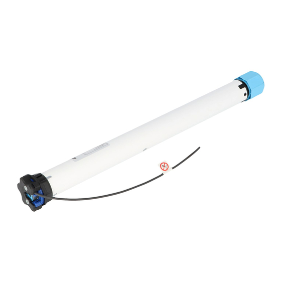
WAREMA WMS roller shutter drive
WAREMA WMS roller shutter drive
Type WMS-RP
Type WMS-RP
Valid from 8 December 2015
Valid from 8 December 2015
Document number 2009231 [Rev. 4 - en]
Document number 2009231 [Rev. 4 - en]
For qualified technicians only
For qualified technicians only
Advertisement
Table of Contents

Related Manuals for WAREMA WMS-RP


Summary of Contents for WAREMA WMS-RP
- Page 1 Setting instructions and Setting instructions and wiring diagram wiring diagram WAREMA WMS roller shutter drive WAREMA WMS roller shutter drive Type WMS-RP Type WMS-RP For qualified technicians only For qualified technicians only Valid from 8 December 2015 Valid from 8 December 2015 Document number 2009231 [Rev.
-
Page 2: Table Of Contents
Table of contents Table of contents Information on safety......................3 Commissioning........................3 Information on the limit positions......................... 3 Aids for commissioning..........................3 Trial run................................. 4 Setting the motor limit positions........................5 Learning a hand-held transmitter into the product............7 Drive description....................... 9 Drive type..............................9 Function of the drive.............................9 Learning/moving to the comfort position................ -
Page 3: Information On Safety
Read through the product instructions before use. Observe all safety and setting instructions. The basic safety instructions INFO can be viewed under (www.warema.de/Sicherheitshinweise). For WMS Hand-held transmitters up to a certain version (see label Rev.D/M on the back), Mode 1 needs to be performed... -
Page 4: Trial Run
Commissioning Trial run Press the DOWN button briefly. The drive stops in the lower limit position. Press the UP button briefly. The drive stops in the upper limit position. The trial run is completed. The next step is "starting the setting procedure" if the limit positions are not correct, or to connect the drive according to the wiring diagram. -
Page 5: Setting The Motor Limit Positions
Commissioning Setting the motor limit positions INFO For commissioning, voltage must be applied to the drive.However, voltage should only be applied to one product at a time. The direction of rotation of the drive is adjusted automatically after "setting the motor limit positions". (see Page When "setting the motor limit positions", the drive is in "dead man's mode"... - Page 6 Commissioning Press the UP button/DOWN button. Move to the lower limit position. "Klack" Press the control button briefly. The drive clicks or jerks briefly. Press the UP button/DOWN button. Move to the upper limit position. Press the control button briefly. The drive waves.
-
Page 7: Learning A Hand-Held Transmitter Into The Product
Learning a hand-held transmitter into the product Learning a hand-held transmitter into the product WMS Hand-held transmitter basic (art. no. 1002953) INFO Only product types of the same type can be operated with a WMS Hand-held transmitter basic. For learning, voltage should only be applied to one receiver. Press the button to wake up the hand-held transmitter. - Page 8 Learning a hand-held transmitter into the product WMS Hand-held transmitter (art. no. 1002767) Press the button to wake up the hand-held trans- mitter. Press the learn button for approx. 5 seconds. lights up green and the transmission LED flashes. Red = new receiver Green = the receiver al- ready belongs to the net- work...
-
Page 9: Drive Description
Drive description Drive description Position feedback The drive notifies the control system of its current position. Drive type Comfort position The drive is designed for 230 V/50 Hz and features an electronic limit switch-off with an integrated radio receiver. An intermediate position of your choice can be stored in the The limit positions are set using a hand-held transmitter, drive and moved to. -
Page 10: Learning/Moving To The Comfort Position
Learning/moving to the comfort position Learning/moving to the comfort position Press the UP button/DOWN button. Move to the desired position. Press the comfort button for approx. 5 s. The transmission LED lights up. Explanation of the colours: Green = position stored Red = procedure failed Briefly press the comfort button . -
Page 11: Wiring Diagram
Degree of protection IP 44 Safety class Short-term operation (S2) 4 min. Limit switch range 64 revolutions Transmission frequency 2.40–2.48 GHz Transmission power < 10 dBm INFO Detailed technical data can be requested from WAREMA. 2009231 [Rev. 4 - en]/2015-12-08 Page 11 | 14... -
Page 12: Possible Faults
Possible faults Possible faults Malfunction: drive does not move Cause Note Remedy No voltage is applied. The transmission LED on the hand- Check the fuse. held transmitter lights up green and then red during operation. Connect the test cable and operate the product with the hand-held transmitter. - Page 13 Malfunction: The drive moves in the outward direction only and moves in the inward direction in steps or in "dead man's mode". Cause Note Remedy The drive limit positions are not set. Set the motor limit positions (Page Malfunction: The drive cannot be learned into the transmitter Cause Note Remedy...
- Page 14 WAREMA Renkhoff SE Hans-Wilhelm-Renkhoff-Straße 2 97828 Marktheidenfeld Germany www.warema.com info@warema.com...
Need help?
Do you have a question about the WMS-RP and is the answer not in the manual?
Questions and answers