Advertisement
Quick Links
Advertisement

Subscribe to Our Youtube Channel
Related Manuals for Netgate XG-7100


Summary of Contents for Netgate XG-7100
- Page 1 Product Manual XG-7100 Netgate Sep 21, 2018...
-
Page 2: Table Of Contents
CONTENTS 1 I/O Ports 2 XG-7100 Switch Overview 3 Getting Started 4 Connecting to Console Port 5 Additional Resources 6 Warranty and Support Information 7 Safety and Legal 8 BIOS Flash Procedure 9 Reinstalling pfSense... - Page 3 Product ManualXG-7100 Thank you for your purchase of the pfSense® XG-7100 Desktop System. This Netgate appliance provides a powerful, reliable, cost-effective solution. Quick Start Guide The Quick Start Guide covers the first time connection procedures and will provide you with the information you need to get your appliance up and running.
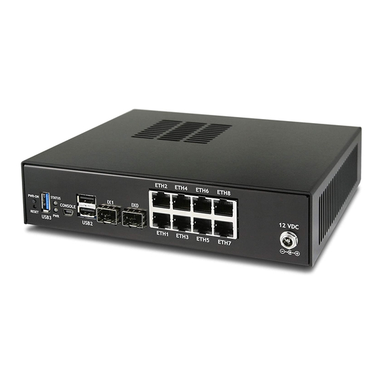
- Page 4 10 Gbps Note: ETH1-8 are switched ports sharing 5 Gbps (2x 2.5 Gbps) to the Intel SoC. These ports can be isolated as an independent interface with the configuration of VLAN tagging as shown in XG-7100 Switch Overview. Warning: There is an Intel-supplied driver issue, which is noted in the...
- Page 5 • 2x USB 2.0 Note: When a graceful shutdown is performed, the XG-7100 Power (PWR) LED will turn red but will stay lit. The Ethernet activity LEDs will turn off. The power supply fan will continue to run. Turning off the rocker switch on the back of the power supply will eliminate all power to the system.
-
Page 6: Xg-7100 Switch Overview
2.1 Interface Links In addition to two SFP+ interfaces, there is also an ethernet switch on the XG-7100. There are eight ethernet ports on this switch that are physically accessible - these interfaces are referred to as ETH1-ETH8. In addition to those 8 ports, there are also three additional ports that operate behind the scenes - PORT 0, PORT 9 (ix2), and PORT 10 (ix3). - Page 7 Product ManualXG-7100 From the operating systems perspective, there are four physical interfaces present: 10Gbps SFP+ 10Gbps SFP+ Gbps (2500-Base-KX, switch link to SoC/CPU) Gbps (2500-Base-KX, switch link to SoC/CPU) 2.2 Switch LAGG ix2 and ix3 (switch uplink ports 9 and 10), are configured as a load-balanced LAGG. This provides an aggregate uplink capable of 5Gbps for ethernet switchports ETH1-8.
- Page 8 Product ManualXG-7100 When data is received on ETH1-8, the switch is capable of utilizing LAGG to determine whether that data should be sent out of PORT 9 or PORT 10. That data then passes over one of two 2.5Gbps switch links (PORT 9/10) to the SoC. Data coming from PORT 9 has a direct line to ix2 and data from PORT 10 has a direct line to ix3.
- Page 9 Product ManualXG-7100 • When data comes into the ETH1 interface, a VLAN tag of 4090 is added to the ethernet frame. • When data comes into interfaces ETH2-8, a VLAN tag of 4091 is added to the ethernet frame. PORT9-10 are configured to act as Trunk ports. •...
- Page 10 Product ManualXG-7100 SWITCH-A PORT ETH1 PORT ETH2 PORT ETH3 PORT ETH4 PORT UPLINK PORT UPLINK SWITCH-B PORT ETH5 PORT ETH6 PORT ETH7 PORT ETH8 SWITCH-A ETH1-4 can talk to each other and to the LAGG uplink. PORT9-10 are members of this switch. . . this is required for this switch to have uplink to pfSense.
- Page 11 Product ManualXG-7100 Selecting Switches from the drop-down will bring up the Switch page with four sections: System Fig. 1: Information on the Marvell 6000 switch LAGGs Ports Information on switchport status and port names. If 802.1q is enabled, this section can also be used to specify the native VLAN ID for each port.
- Page 12 Product ManualXG-7100 Fig. 2: Information on members of the switch LAG Fig. 3: 802.1q enabled (default) Fig. 4: Port VLAN Mode 2.4. Configuring the Switch...
- Page 13 Product ManualXG-7100 Fig. 5: 802.1q enabled (default) Fig. 6: Port VLAN Mode 2.4. Configuring the Switch...
- Page 14 Product ManualXG-7100 2.4.2 Interfaces Section There is also relevant configurations under Interfaces -> Assignments. Interface Assignments Under Interface Assignments, notice LAGG0 (UPLINK) is displayed as an available port but is not enabled in the list of interfaces. This is because the default configuration is only expecting VLAN tagged traffic so the VLAN child interface 4090 and 4091 are enabled instead.
- Page 15 This is what the default interface assignments look like on a XG-7100 without an addon NIC: In this example, ix0 will be WAN, so select option 1 to re-assign WAN from lagg0.4090 to ix0:...
- Page 16 Product ManualXG-7100 No additional VLANs are needed for this, so enter n to continue. Input ix0 as the new WAN interface name: Input the same default LAN interface of lagg0.4091 for the LAN interface name and press Enter to complete the interface reassignment: 2.5.
- Page 17 Product ManualXG-7100 The interface assignments should show like this now: At this point SFP+ port ix0 is now configured as the WAN interface. The LAN interface is still configured the same as the default. Next, the switch will need to be updated so that ETH1 (previously WAN) acts the same as ETH2-8. This will be done from the webGUI.
- Page 18 Product ManualXG-7100 VLAN 4090 is no longer needed since WAN is dedicated to ix0 now. You can either select on the row containing 4090 to delete this entry, or click to remove port 1 as a member: For this example, I simply removed VLAN 4090 from the switch with .
- Page 19 Product ManualXG-7100 Next, update the PVID for ETH1 so that it uses VLAN 4091 rather than the old VLAN 4090. To do this, click on the Ports tab and click on the 4090 Port VID to modify it: Then click on Save: 2.5.
- Page 20 Product ManualXG-7100 At this point, everything should be configured properly. ETH1-8 will act as a single LAN switch. One final step that should be performed is to remove the old VLAN 4090 from pfSense. So far VLAN 4090 was only removed from the switch.
- Page 21 Product ManualXG-7100 Add, enable, and configure the VLAN interface under Interfaces Assignments: 2.5. Switch Configuration Examples...
- Page 22 Product ManualXG-7100 Also create any necessary firewall rules under Firewall -> Rules. Now that pfSense knows of this new VLAN network, configure the switch so that ETH1-4 use the new network. To do this, go to Interfaces -> Switches -> VLANs and click the Add Tag button. Input the VLAN tag for the new network (same as the VLAN ID configured in the previous steps) and add ETH1-4 and PORT9-10 (uplinks) as members.
- Page 23 Product ManualXG-7100 Once this is done, click the Save button. The final result should look like this: Lastly, update the Port VIDs to use the new 4081 VLAN rather than 4091 on ETH1-4 and click Save: 2.5. Switch Configuration Examples...
- Page 24 Product ManualXG-7100 Now ETH1-4 act as a switch for the VLAN 4081 LAN and ETH5-8 act as a switch for the VLAN 4091 LAN. 2.5.3 Trunking VLAN tagged traffic For expanding on the previous example, let’s assume there is a management VLAN of 4000 where devices are already tagged on this VLAN prior to hitting pfSense.
- Page 25 Product ManualXG-7100 Untagged traffic on ETH8 will be assigned a VLAN ID of 4091. ETH8 and the uplinks will also accept traffic that has already been tagged with a VLAN ID of 4000 as well. 2.5. Switch Configuration Examples...
-
Page 26: Getting Started
Tip: Before configuring the pfSense appliance it is best to activate it by following the instructions at https://www. netgate.com/register/. The basic firewall configuration begins with connecting the pfSense appliance to the Internet. Neither the modem nor the pfSense appliance should be powered up at this time. - Page 27 Product ManualXG-7100 3.2 Logging Into the Web Interface Browse to https://192.168.1.1 to access the web interface. In some instances, the browser may respond with a message indicating a problem with website security. Below is a typical example in Google Chrome. If this message or similar message is encountered, it is safe to proceed.
- Page 28 Product ManualXG-7100 3.4 Configuring Hostname, Domain Name and DNS Servers 3.5 Hostname For Hostname, any desired name can be entered as it does not affect functionality of the firewall. Assigning a hostname to the firewall will allow the GUI to be accessed by hostname as well as IP address. For the purposes of this guide, use pfsense for the hostname.
- Page 29 Product ManualXG-7100 connections and the ISP automatically assigns DNS server IP addresses. When using a static IP on WAN, DNS server IP addresses must be entered here for name resolution to function if the default DNS Resolver settings are not used. DNS servers can be specified here even if they differ from the servers assigned by the ISP.
- Page 30 Product ManualXG-7100 This depicts the four possible WAN interface types. Static, DHCP, PPPoE and PPTP. One must be selected from the drop-down list. Further information from the ISP is required to proceed when selecting Static, PPPoE and PPTP such as login name and password or as with static addresses, an IP address, subnet mask and gateway address.
- Page 31 Product ManualXG-7100 3.14 Configuring DHCP Hostname Some ISPs specifically require a DHCP Hostname entry. Unless the ISP requires the setting, leave it blank. 3.15 Configuring PPPoE and PPTP Interfaces Information added in these sections is assigned by the ISP. Configure these settings as directed by the ISP 3.14.
- Page 32 Product ManualXG-7100 3.16 Block Private Networks and Bogons When enabled, all private network traffic originating on the internet is blocked. Private addresses are reserved for use on internal LANs and blocked from outside traffic so these address ranges may be reused by all private networks. The following inbound address Ranges are blocked by this firewall rule: •...
- Page 33 Product ManualXG-7100 3.17 Configuring LAN IP Address & Subnet Mask A static IP address of 192.168.1.1 and a subnet mask (CIDR) of 24 was chosen for this installation. If there are no plans to connect this network to any other network via VPN, the 192.168.1.x default is sufficient. Click Next to continue.
- Page 34 Product ManualXG-7100 3.19 Save Changes Click Reload to save configuration. 3.20 Basic Firewall Configured To proceed to the webConfigurator, make the selection as highlighted. The Dashboard display will follow. 3.21 Backing Up and Restoring At this point, basic LAN and WAN interface configuration is complete. Before proceeding, backup the firewall con- figuration.
- Page 35 Product ManualXG-7100 Click Download Configuration and save a copy of the firewall configuration. This configuration can be restored from the same screen by choosing the backup file under Restore configuration. 3.21. Backing Up and Restoring...
- Page 36 Product ManualXG-7100 3.22 Connecting to the Console There are times when accessing the console is required. Perhaps GUI console access has been locked out, or the password has been lost or forgotten. See also: Connecting to Console Port Connect to the console. Cable is required. 3.22.
-
Page 37: Connecting To Console Port
CHAPTER FOUR CONNECTING TO CONSOLE PORT 4.1 Simple Configuration Below are the simple instructions for connecting to the console port with Microsoft Windows. If these steps do not work for you or if you’re an operating system other than Windows, then please skip forward to Advanced Configura- tion. - Page 38 Product ManualXG-7100 Open PuTTY and locate the Session display as shown below. For the Connection type, select Serial. Set Serial line to the COM Port that is displayed in Windows Device Manager, COM4 for this example, and the Speed to 115200 bits per second, the speed of the BIOS in this case.
- Page 39 Product ManualXG-7100 Select Open and the console screen will be displayed. 4.2 Advanced Configuration A Silicon Labs CP210x USB-to-UART bridge is used to provide access to the serial port that acts as a system console. This is exposed via a USB Mini-b (5-pin) port on the front of the case. There are several steps required to access the system console via this port.
- Page 40 Product ManualXG-7100 Loading the Linux Driver If the device does not appear automatically, the CP210x driver module may need to be loaded manually, especially if the version of Linux being run is not recent. If the driver was provided with the Linux distribution, run modprobe cp210x as root or using sudo.
- Page 41 Product ManualXG-7100 FreeBSD The device associated with the system console is likely to show up as /dev/cuaU1. Look for messages about the device attaching in the system log files or by running dmesg. 4.2.4 Launch a Terminal Program Use a terminal program to connect to the system console port. PuTTY is a popular terminal program that is available on various operating systems.
- Page 42 Product ManualXG-7100 Window Columns x Rows = 80x24 Window > Appearance Font = Courier New 10pt or Consolas 10pt Window > Translation Remote Character Set = Use font encoding or UTF-8 Window > Translation Handling of line drawing characters = Use font in both ANSI and OEM modes or Use Unicode line drawing code points Window >...
- Page 43 Product ManualXG-7100 Serial Output Stops After the BIOS If serial output is shown for the BIOS but stops afterward, check the following items: • Ensure the terminal program is configured for the correct speed for the installed operating system. (See “No Serial Output”...
-
Page 44: Additional Resources
5.2 Netgate Training Netgate training offers training courses for increasing your knowledge of pfSense products and services. Whether you need to maintain or improve the security skills of your staff or offer highly specialized support and improve your customer satisfaction;... -
Page 45: Warranty And Support Information
CHAPTER WARRANTY AND SUPPORT INFORMATION • One year manufacturer’s warranty. • Please contact Netgate for warranty information or view our Product Lifecycle page. • All Specifications subject to change without notice For support information, view our support plans. -
Page 46: Safety And Legal
CHAPTER SEVEN SAFETY AND LEGAL Contents • Safety and Legal – Safety Notices – Electrical Safety Information – FCC Compliance – Industry Canada – Australia and New Zealand – CE Marking – RoHS/WEEE Compliance Statement – Declaration of Conformity – Disputes –... - Page 47 Product ManualXG-7100 7.2 Electrical Safety Information 1. Compliance is required with respect to voltage, frequency, and current requirements indicated on the manu- facturer’s label. Connection to a different power source than those specified may result in improper operation, damage to the equipment or pose a fire hazard if the limitations are not followed. 2.
- Page 48 Product ManualXG-7100 7.6 CE Marking CE marking on this product represents the product is in compliance with all directives that are applicable to it. 7.7 RoHS/WEEE Compliance Statement 7.7.1 English European Directive 2002/96/EC requires that the equipment bearing this symbol on the product and/or its packaging must not be disposed of with unsorted municipal waste.
- Page 49 7.8 Declaration of Conformity 7.8.1 ˇ Cesky[Czech] NETGATE tímto prohla uje, e tento NETGATE device, je ve shod se základními po adavky a dal ími p íslu n mi ustanoveními sm rnice 1999/5/ES. 7.8.2 Dansk [Danish] Undertegnede NETGATE erklærer herved, at følgende udstyr NETGATE device, overholder de væsentlige krav og...
- Page 50 Alulírott, NETGATE nyilatkozom, hogy a NETGATE device, megfelel a vonatkozó alapvetõ követelményeknek és az 1999/5/EC irányelv egyéb elõírásainak. 7.8.10 Íslenska [Icelandic] Hér me l sir NETGATE yfir ví a NETGATE device, er í samræmi vi grunnkröfur og a rar kröfur, sem ger ar eru í tilskipun 1999/5/EC. 7.8.11 Italiano [Italian] Con la presente NETGATE dichiara che questo NETGATE device, è...
- Page 51 Product ManualXG-7100 7.8.16 Slovensky [Slovak] NETGATE t mto vyhlasuje, e NETGATE device, sp a základné po iadavky a v etky príslu né ustanovenia Smernice 1999/5/ES. 7.8.17 Svenska [Swedish] Härmed intygar NETGATE att denna NETGATE device, står I överensstämmelse med de väsentliga egenskapskrav och övriga relevanta bestämmelser som framgår av direktiv 1999/5/EG.
- Page 52 4616 West Howard Lane, Suite 900 Austin, Texas 78728 legal@netgate.com The arbitration will be conducted by the American Arbitration Association (AAA) under its rules. The AAA’s rules are available at www.adr.org. Payment of all filing, administration and arbitrator fees will be governed by the AAA’s rules.
- Page 53 Product ManualXG-7100 THE PRODUCTS/SERVICES AND ALL INFORMATION, CONTENT, MATERIALS, PRODUCTS (INCLUD- ING SOFTWARE) AND OTHER SERVICES INCLUDED ON OR OTHERWISE MADE AVAILABLE TO YOU THROUGH THE PRODUCTS/SERVICES ARE PROVIDED BY US ON AN “AS IS” AND “AS AVAILABLE” BA- SIS, UNLESS OTHERWISE SPECIFIED IN WRITING. WE MAKE NO REPRESENTATIONS OR WARRANTIES OF ANY KIND, EXPRESS OR IMPLIED, AS TO THE OPERATION OF THE PRODUCTS/SERVICES, OR THE INFORMATION, CONTENT, MATERIALS, PRODUCTS (INCLUDING SOFTWARE) OR OTHER SERVICES INCLUDED ON OR OTHERWISE MADE AVAILABLE TO YOU THROUGH THE PRODUCTS/SERVICES, UN-...
-
Page 54: Bios Flash Procedure
4. When the installation is complete a message will appear saying: pfSense-pkg-Netgate_Coreboot_Upgrade installation successfully completed 5. Now that the package is installed, navigate to System -> Netgate Coreboot Upgrade. 6. This page will show you the latest version of Coreboot available and the current version that is running on the system. -
Page 55: Reinstalling Pfsense
Note: The pfSense factory version is the version that is preinstalled on units purchased from Netgate. The factory image is optimally tuned for our hardware and contains some features that cannot be found elsewhere, such as the AWS VPN Wizard. - Page 56 Product ManualXG-7100...
Need help?
Do you have a question about the XG-7100 and is the answer not in the manual?
Questions and answers