Advertisement
Quick Links
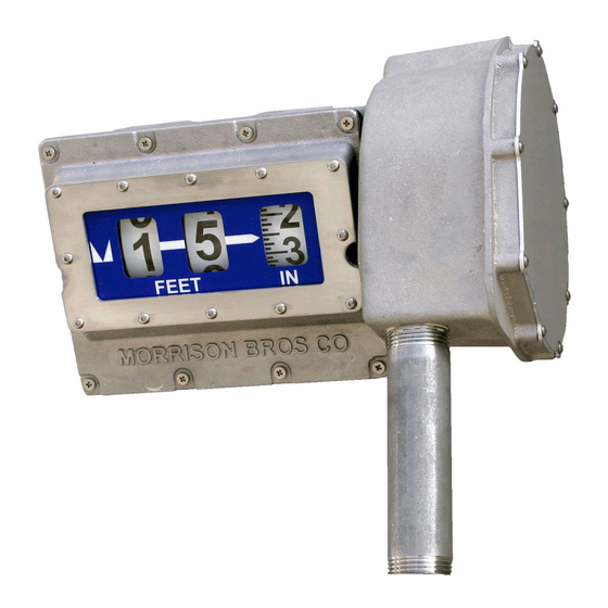
1518/1519 Metric Mechanical Gauge
Installation, Operation, and Maintenance Instructions
The 1518M/1519M Mechanical Gauge is designed to be used to measure liquid level in an aboveground storage
tank. The gauge mounts to the top of the tank and is activated by a float connected to a cable. The 1519M
provides a single level alarm relay output, NO or NC, configurable to the desired level. The alarm relay output
!
requires an external alarm box, such as the 918 or 918AC series alarm boxes.
Failure to follow any or all of the warnings and instructions in this document could result in a hazardous
liquid spill, which could result in property damage, environmental contamination, fire, explosion, serious
injury or death.
NOTE: The most accurate method to calibrate the tank is with fluid in it. This will take into account variables
associated with the float position, the mechanism, and the fluid density.
Installation
!
WARNINGS
• Fire Hazard – Death or serious injury could result from spilled liquids.
• Any modification to this gauge other than those stated in these installation instructions will void the product
warranty.
• This device is intended to be used as a liquid level indicator to the operator and should not be the only system
in place to prevent a tank from overfilling. It is the sole responsibility of the operator to continuously prevent
any spillage regardless of the situation or status of the gauge.
• Install in accordance with all applicable local, state and federal laws.
• For your safety, it is important to follow local, state, federal and/or OSHA rules that apply to working inside,
above, or around the storage tank and piping area. Use all personal protective equipment required for
working in the specific environment.
• Tanks could be under pressure. Vapors could be expelled from tank vents, piping, valves or fittings while
performing installation. Vapors could catch fire or cause an explosion. Avoid sparks, open flame, or hot tools
when working on gauge.
• Use a dampened cloth when cleaning the clear front cover of the gauge to prevent static buildup and
discharge.
• In the event of malfunction, contact Morrison Bros. Customer Service.
Steps
1. Verify contents of box. You should have received the gauge, float, and a small tube of adhesive (See Figure
1). Inspect the items for shipping damage. DO NOT use if damage is found.
2. Remove the front cover of gauge and remove foam under cover. NOTE: The Philips screws in the front
cover are captive fasteners that aren't meant to be removed. Place the front
cover back on gauge. Place the front cover back on gauge. The gauge
should be reading approximately 111 centimeters. If not, the gauge could
be damages or dysfunctional. Inspect the internals for any damage. DO
NOT use if damage is found. Find the cable sticking out of the end of the
gauge connection pipe. Slowly pull on cable to ensure gauge is functioning
properly. DO NOT pull and release cable uncontrollably. This can cause
damage to the internal mechanism and render the gauge inoperable.
ALWAYS hold onto cable and allow it to move in
a slow steady motion.
3. Remove the red warning tag
4. If installing a 1519M gauge, refer to page 3 for calibrating alarm set point.
5. Locate the opening on the top of the tank where the gauge is to be installed (minimum opening size is 2"
schedule 40 pipe). If possible, select a location away from the fill port to avoid excessive turbulence that
could affect the float. Also make certain that there are no objects inside the tank, near the selected opening,
upon which the float and cable could get tangled and that the gauge location will not interfere with normal
operation of the tank.
rev. 07‑29‑2021
PARTS LISTING
NO.
DESCRIPTION
MATERIAL
1
TEST LINE TEST LINE
BRASS/STAINLESS STEEL/VITON
PARTS LISTING
NO.
PART NUMBER
DESCRIPTION
MATERIAL
QTY
1
1618--0101 MHCC INDICATOR WHEEL HOUSING-MACHINED
ALUMINUM
1
2
1518M-0108 AP
ASSEMBLED FRONT PANEL
1
3
1518--0102 MHCC CABLE REEL HOUSING-MACHINED
ALUMINUM
1
4
1618--0130 21
GEAR SHAFT
STAINLESS STEEL 1
5
1618--0116 21
O-RING BUSHING
STAINLESS STEEL 1
6
1518M-0060 AR
CABLE REEL ASSEMBLY
1
7
1518M-0107 AW
INDICATOR WHEEL ASSEMBLY
1
8
1618--0112 2P
SHAFT CLAMP
ALUMINUM
3
9
1618--0169 2S
SCREW - PAN HEAD
STAINLESS STEEL 15
10
1618--0129 2C
CABLE REEL COVER
ALUMINUM
1
11
1618--0163 2S
SEALING SCREW
ALUMINUM
3
12
1618--0146 2P
HAIRPIN COTTER PIN
STAINLESS STEEL 1
13
1518--0104 2N
PIPE NIPPLE
STAINLESS STEEL 1
14
1218S-2535 2R
RETAINING RING
STAINLESS STEEL 2
15
1518--0103 21
CABLE BUSHING
PTFE
1
16
1618--0104 21
GEAR-MACHINED
2
17
718---0218 2S
MULTISEAL
1
18
1618--0136 2R
CABLE REEL COVER O-RING
1
19
1618--0164 2R
CABLE REEL HOUSING O-RING
1
Gauge
Figure 1
Morrison Bros. Co. ‑ Dubuque, IA ‑ 800‑553‑4840
PARTS LISTING
NO.
PART NUMBER
DESCRIPTION
MATERIAL
QTY
1
1218S-2535 2R
RETAINING RING
2
2
1518--0102 MHCC CABLE REEL HOUSING-MACHINED
1
3
1518--0103 21
CABLE BUSHING
1
4
1518--0104 2N
PIPE NIPPLE
1
5
1518M-0060 AR
CABLE REEL ASSEMBLY
1
6
1518M-0107 AW
INDICATOR WHEEL ASSEMBLY
1
7
1518M-0108 AP
ASSEMBLED FRONT PANEL
1
8
1618--0101 MHCC INDICATOR WHEEL HOUSING-MACHINED
1
9
1618--0104 21
GEAR-MACHINED
2
10
1618--0112 2P
SHAFT CLAMP
3
11
1618--0116 21
O-RING BUSHING
1
12
1618--0129 2C
CABLE REEL COVER
1
13
1618--0130 21
GEAR SHAFT
1
14
1618--0136 2R
CABLE REEL COVER O-RING
1
15
1618--0146 2P
HAIRPIN COTTER PIN
1
16
1618--0163 2S
SEALING SCREW
3
17
1618--0164 2R
CABLE REEL HOUSING O-RING
1
18
1618--0169 2S
SCREW - PAN HEAD
15
19
718---0218 2S
MULTISEAL
1
1
7
8
9
13
15
14
GAUGE HEAD
STANDARD TOLERANCES
UNLESS OTHERWISE SPECIFIED
METRIC MECHANICAL TANK
1 PL DECIMAL
.1
2 PL DECIMAL
.015
3 PL DECIMAL .005
ANGULAR
1
CASTING .025
FIG. NO. 1518M
SURFACE FINISH 125MICRO INCH RMS MAX
.035 INSIDE RADIUS MAX
.065 OUTSIDE RADIUS MAX
SCALE
MATERIAL:
BREAK AND DEBURR ALL SHARP EDGES
SEE PART I.D. CH
DIMENSIONS ARE IN INCHES/ALL DIMENSIONS SHOWN ARE PRIOR TO ANY COATING
1/2
THE INFORMATION CONTAINED IN THIS DRAWING IS THE SOLE PROPERTY OF MORRISON BROS. CO. TO BE USED ONLY F
CONFIDENTIAL:
PURPOSE EXPLICITLY DIRECTED BY MORRISON BROS. CO. ANY REPRODUCTION IN PART OR AS A WHOLE WITHOUT THE
PERMISSION OF MORRISON BROS. CO. IS PROHIBITED
1
1518M‑0105 PP
REV
A
16
Advertisement

Related Manuals for Morrison Bros. co. 1518


Summary of Contents for Morrison Bros. co. 1518
- Page 1 RETAINING RING • Use a dampened cloth when cleaning the clear front cover of the gauge to prevent static buildup and TEST LINE TEST LINE BRASS/STAINLESS STEEL/VITON 1518--0102 MHCC CABLE REEL HOUSING-MACHINED 1518--0103 21 CABLE BUSHING 1518--0104 2N PIPE NIPPLE discharge.
- Page 2 PARTS LISTING 1218S-2535 2R RETAINING RING 7. Carefully lay the gauge on the top of the tank, near your DESCRIPTION MATERIAL 1518--0102 MHCC CABLE REEL HOUSING-MACHINED selected tank opening. TEST LINE TEST LINE BRASS/STAINLESS STEEL/VITON 1518--0103 21 CABLE BUSHING 8. Attach the necessary pipe bushing to adapt the 1” gauge...
- Page 3 Failure to follow any or all of the warnings and instructions in this document could result in a hazardous liquid spill, which could result in property damage, environmental contamination, fire, explosion, serious injury or death. 1519M Calibrating the Alarm Set Point 1.
- Page 4 9. Push the indicator wheel to the left again, disengaging the wheel from the drive gear. Rotate the wheel upwards to the other magnet pockets. Place a screw through the magnet into the positioner and while holding the indicator wheel, thread into the indicator wheel. DO NOT OVER TIGHTEN, only snug up the screw.
- Page 5 6. Connect the cable wires at the Gauge Head and Power Module ends of the cable as laid out in Table 1. a. Remove approximately 6 inches of the outer jacket of the System Cable. b. Entirely remove the foil shield and the associated drain wire. c.
- Page 6 8. Run wires between the Dry Contact output of the Gauge Head and the associated Tank Alarm (see Table 1). Choose the contact type as is appropriate for the Tank Alarm to be used. NOTE: There are eight (8) wires available in the junction box attached to the bottom of the gauge head. Five (5) of these are wired to the Power Module.
- Page 7 Figure 17—Connecting the Battery 4. Connect the Battery Cable to the Power Module Board’s J4 connector in the upper right hand corner of the board. The front panel LED should flash momentarily if the system is alive. If this does not happen, disconnect the battery and check all wiring connections in the system before proceeding.
-
Page 8: Operation
1519M Verify Installation For a 1519M, gauge the system must be tested before installation is completed. 1. Remove the pipe plug and grab onto the cable (See Figure 20.) 2. To test a high-level alarm, slowly begin pulling downwards on the cable causing the float to rise in the tank, this whole time the gauge should be taking up the slack in the cable. -
Page 9: Maintenance
Maintenance WARNINGS • Fire Hazard – Death or serious injury could result from spilled liquids. • You must be trained to maintain this gauge. Stop now if you have not been trained. • For your safety, it is important to follow local, state, federal and/or OSHA rules that apply to working inside, above, or around the storage tank and piping area.
Need help?
Do you have a question about the 1518 and is the answer not in the manual?
Questions and answers