Table of Contents
Advertisement
Quick Links
VW
vehicles with Discover Media/Pro MIB3 infotainment
Skoda
vehicles with MIB3 Bolero/Columbus infotainment
Seat/Cupra
infotainment and 10 or 12inch monitor
Video-inserter for front- and rear-view camera
Product features
Video-inserter for factory-infotainment systems
1 CVBS Input for rear-view camera
1 CVBS Input for front camera
2 CVBS Video-inputs for after-market Video sources (e.g. USB-Player, DVB-T Tuner)
Automatic switching to rear-view camera input on engagement of the reverse gear
Automatic front camera switching after reverse gear for 10,15 or 20 seconds
(adjustable)
Activatable parking guide lines for rear-view camera (not available for all vehicles)
Video-in-motion (ONLY for connected video-sources)
Video-inputs NTSC and PAL compatible
Version 27.08.2021
Video inserter
RL4-MIB100
Compatible with
and 10inch monitor
and 10inch monitor
vehicles with MIB3 Media System Plus
and two more video inputs
HW: CAM(V100)/(V20)
RL4-MIB100
Advertisement
Table of Contents

Related Manuals for Caraudio-Systems RL4-MIB100


Summary of Contents for Caraudio-Systems RL4-MIB100
- Page 1 Video inserter RL4-MIB100 Compatible with vehicles with Discover Media/Pro MIB3 infotainment and 10inch monitor Skoda vehicles with MIB3 Bolero/Columbus infotainment and 10inch monitor Seat/Cupra vehicles with MIB3 Media System Plus infotainment and 10 or 12inch monitor Video-inserter for front- and rear-view camera...
-
Page 2: Table Of Contents
2.6. Connection - video-interface and external keypad 2.7. Picture settings and guide lines 3. Interface operation 3.1. By factory infotainment button 3.2. By keypad 4. Specifications 5. FAQ – Trouble Shooting-Interface functions 6. Technical support Version 27.08.2021 HW: CAM(V100)/(V20) RL4-MIB100... -
Page 3: Prior To Installation
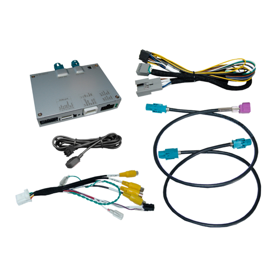
Due to changes in the production of the vehicle manufacturer there’s always a possibility of incompatibility. 1.1. Delivery contents Take down the serial number of the interface and store this manual for support purposes: ____________________ Version 27.08.2021 HW: CAM(V100)/(V20) RL4-MIB100... -
Page 4: Checking The Compatibility Of Vehicle And Accessories
The front camera will automatically be switched for 10, 15 or 20 seconds (adjustable) after disengaging the reverse gear. A manually front camera switching is possible by external keypad. Guidelines and PDC Displayed guidelines and PDC are not available in all vehicles. Version 27.08.2021 HW: CAM(V100)/(V20) RL4-MIB100... -
Page 5: Boxes And Connectors - Video Interface
Further it reads the vehicle’s digital signals out of the vehicle’s CAN-bus and converts them for the video interface. Version 27.08.2021 HW: CAM(V100)/(V20) RL4-MIB100... -
Page 6: Settings - 8 Dip Switches (Black)
*The front camera will automatically be switched for 10, 15 or 20 seconds after disengaging the reverse gear (according to the menu adjustments). After each Dip-switch-change a power-reset of the Video interface has to be performed! See the following chapters for detailed information. Version 27.08.2021 HW: CAM(V100)/(V20) RL4-MIB100... -
Page 7: Activating The Front Camera (Dip 1)
PDC (if available) as „picture in picture“ in combination with the camera image. For a detailed description, see chapter "Switching the Camera Image Formats and Factory PDC Display ". Dip switches 4 and 8 are out of function and have to be set to OFF. Version 27.08.2021 HW: CAM(V100)/(V20) RL4-MIB100... - Page 8 According to the diagram below, a diagonal dip-switch position has to be avoided under any circumstances! Manufacturer head unit Dip 1 Dip 2 Setting 1 OFF ↓ OFF ↓ Setting 2 ON ↑ ON ↑ After each Dip-switch-change a power-reset of the video interface has to be performed! Version 27.08.2021 HW: CAM(V100)/(V20) RL4-MIB100...
-
Page 9: Installation
The interface needs a permanent 12V source! 2.1. Place of installation The interface is supposed to be installed at a suitable location behind the vehicle`s head- unit. Version 27.08.2021 HW: CAM(V100)/(V20) RL4-MIB100... -
Page 10: Connection Schema
2.2. Connection schema Version 27.08.2021 HW: CAM(V100)/(V20) RL4-MIB100... -
Page 11: Connection - Factory Head Unit
HSD+2 connector "HU IN" of the video interface. Connect the opposite female waterblue HSD connector of the enclosed picture signal cable-2 to the previously become free male pink coloured HSD connector of the head unit. Version 27.08.2021 HW: CAM(V100)/(V20) RL4-MIB100... -
Page 12: Connection - Quadlock - Can
Clip in the grey coloured female 12pin connector of the PNP harness in the previously become free position of the female Quadlock connector. After that, finish the Quadlock reconnection at the rear-side of the head-unit. Version 27.08.2021 HW: CAM(V100)/(V20) RL4-MIB100... -
Page 13: Connection - Power
2.3.3. Connection - Power Connect the single yellow wire of the 10pin power/CAN cable to +12V permanent and stabile power supply. Connect the single black wire of the 10pin power/CAN cable to the vehicle’s negative ground. Version 27.08.2021 HW: CAM(V100)/(V20) RL4-MIB100... -
Page 14: Analog Power Supply
If, after connecting the PNP harness, no interface LED lightens up while the ignition is turned on, the purple-coloured wire Manual ACC of the 12pin interface cable has to be connected additionally to S-contact terminal 86s +12V (e.g. glove compartment illumination). Version 27.08.2021 HW: CAM(V100)/(V20) RL4-MIB100... -
Page 15: Power Supply Output For 2.5. Connection - Video-Sources
+12V (max. 3A) when reverse gear is engaged incl. 10, 15 or 20 seconds delay* after reverse gear is disengaged and +12V by manual switching to front camera by keypad (short press) Dip 1 OFF +12V (max. 3A) ACC Version 27.08.2021 HW: CAM(V100)/(V20) RL4-MIB100... - Page 16 Connect the front camera’s video RCA connector to the 12pin interface cable’s female RCA connector „Front V3“. Connect the video RCA of the AV source 1 and 2 to the 12pin interface cable’s female RCA connector “Left (V1)” ”Right (V2)”. Version 27.08.2021 HW: CAM(V100)/(V20) RL4-MIB100...
-
Page 17: Audio Insertion
The power supply output gives +12V then, as well (if Dip 1 is set to ON and the front camera input is selected). Attention: A long press of the external keypad push button will switch the interface to the next source. Version 27.08.2021 HW: CAM(V100)/(V20) RL4-MIB100... -
Page 18: After-Market Rear-View Camera
“V4 Reverse” while the reverse gear is engaged. Additionally, the +12V (max. 3A) power supply for the rear-view camera can be taken from the green wire of the 12pin interface cable. Version 27.08.2021 HW: CAM(V100)/(V20) RL4-MIB100... -
Page 19: Case 2Interface Does Not Receive The Reverse Gear Signal
Connect the output connector (87) of the relay to the rear-view camera’s power- cable, like you did it to the green “Reverse-IN” cable before. Connect stabile and permanent +12V to the relay’s input connector (30). Version 27.08.2021 HW: CAM(V100)/(V20) RL4-MIB100... -
Page 20: Connection - Video-Interface And External Keypad
Connect the female 4pin connector of the keypad to the male 4pin connector of the 12pin interface cable. Note: Even if switching through several video sources by the keypad mightn’t be required, the invisible connection and availability is strongly recommended. Version 27.08.2021 HW: CAM(V100)/(V20) RL4-MIB100... -
Page 21: Picture Settings And Guide Lines
Note: If there is no communication between interface and the vehicle`s CAN-bus (several vehicles aren’t compatible), the reverse gear guide-lines can`t be shown during the vehicle’s operation, even if they once appear after having switched the system to powerless! Version 27.08.2021 HW: CAM(V100)/(V20) RL4-MIB100... -
Page 22: Interface Operation
Each press will switch to the next enabled input. Inputs which are not enabled will be skipped. Switchover by vehicle buttons isn’t possible in all vehicles. In some vehicles the external keypad has to be used. Version 27.08.2021 HW: CAM(V100)/(V20) RL4-MIB100... -
Page 23: By Keypad
7V - 25V Stand-by power drain 10mA Power 270mA @12V Video input 0.7V - 1V Video input formats NTSC/PAL Temperature range -40°C to +85°C Dimensions video-box 117 x 27 x 103 mm (W x H x D) Version 27.08.2021 HW: CAM(V100)/(V20) RL4-MIB100... -
Page 24: Faq - Trouble Shooting-Interface Functions
Camera input picture fluorescent light which shines Test camera under natural light outside the garage. flickers. directly into the camera. Camera input picture is Protection sticker not Remove protection sticker from lens. bluish. removed from camera lens. Version 27.08.2021 HW: CAM(V100)/(V20) RL4-MIB100... -
Page 25: Technical Support
Please note that direct technical support is only available for products purchased directly from NavLinkz GmbH. For products bought from other sources, contact your vendor for technical support. NavLinkz GmbH distribution/tech dealer-support Heidberghof 2 D-47495 Rheinberg +49 2843 17595 00 Email mail@navlinkz.de 10R-05 0068 Made in China Version 27.08.2021 HW: CAM(V100)/(V20) RL4-MIB100...
Need help?
Do you have a question about the RL4-MIB100 and is the answer not in the manual?
Questions and answers