
Related Manuals for Stealth Cam STC-V650


Summary of Contents for Stealth Cam STC-V650
- Page 1 STC-V650 User’s Manual Toll Free Customer Support 1-877-269-8490 www.stealthcam.net Version 1.0 1/08...
- Page 2 Stealth Cam Limited Warranty Your Stealth Cam scouting camera is covered by a 90 days Limited Warranty on parts and labor from the date of original purchase, and purchases must be made through an authorized dealer. The warranty covers defects in workmanship and materials.
-
Page 3: Manual Contents
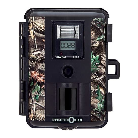
STC-V650 Manual Contents Camera overview Picture capacity chart Camera kit contents Battery and memory Installation Definition Set up and programming Using the camera Mounting the camera Viewing & Deleting images Using external solar power Memory compatibility chart Technical Specs General Information Moon Phase symbol chart www.stealthcam.net... - Page 4 STC-V650 Camera overview Front housing image with major parts indication. www.stealthcam.net Toll Free 877-269-8490...
- Page 5 STC-V650 Open view image with major parts indication: www.stealthcam.net Toll Free 877-269-8490...
- Page 6 STC-V650 Side view with major parts indication: www.stealthcam.net Toll Free 877-269-8490...
- Page 7 STC-V650 Picture / Image Capacity SD card High Base 16MB 32MB 64MB 128MB 1280 256MB 2560 512MB 1280 1 GB 1088 2560 10240 2 GB 1024 2176 5120 20480 NOTE: Picture / Image Capacity Chart provides approximate number of images or AVI movies based on resolution setting and the size of memory card.
- Page 8 STC-V650 Camera kit contents Model STC-V650 Sniper Digital Scouting Camera • User Manual • USB cable • Mounting Strap • www.stealthcam.net Toll Free 877-269-8490...
- Page 9 Doing so will damage the camera and will void the warranty. The Stealth Cam STC-V650 Sniper Advanced Digital Scouting Camera is designed to operate using two different types of battery power options.
- Page 10 STC-V650 12V Lead Acid external battery The STC-V650 is equipped with an external power jack designed to accept a barrel plug cable to attach to a sealed lead acid battery. (sold separately). This will enhance the camera’s field life. Battery cable and complete 12V Lead Acid battery kits are available wherever Stealth Cam scouting cameras are sold or call toll free 877-269-8490.
- Page 11 STC-V650 Memory Options Your STC-V650 camera is equipped with 32MB built in flash memory. The camera is also equipped with an expandable media card slot capable of accepting up to 2GB SD card (sold separately). With no memory card inserted into the slot, the camera will use the built in 32MB memory.
- Page 12 STC-V650 SD cards must be clean (no images from other sources). If you are using the SD card from other cameras, please make sure to format the SD card in your computer using FAT formatting, not FAT32, prior to use in the camera.
- Page 13 STC-V650 Definitions Time out: To set the amount of time in minutes the camera will • sleep between PIR triggering. Flash: • Auto – Flash on based on surrounding light conditions. Off – Turn off the flash. Capture mode: •...
- Page 14 STC-V650 (Low image quality) o 0.3M: Select this option to capture a 0.3 mega pixels image. (Base image quality) o Video resolution (320 x 240): This is the resolution during video capturing. Batteries Status: It shows the battery status. •...
- Page 15 STC-V650 Moon phase and Temperature: Displays the moon phase and • temperature. PIR Far/Near dial: Adjusts the PIR detection sensitivity. • Near is 19 feet Far is 30 feet www.stealthcam.net Toll Free 877-269-8490...
-
Page 16: Setup And Programming
STC-V650 Set up and Programming When the camera is first turned on, the internal LCD screen displays the camera status. The following information is displayed on this screen. Flash Mode Control: The camera is pre-programmed with Auto Flash setting. Switch the camera to ON position. - Page 17 UP or DOWN button until the status screen appears. Programming the Stealth Cam STC-V650 Switch the camera to the ON position. Once the Camera status screen is visible, press the MENU button. This will bring up the SETTING screen.
- Page 18 STC-V650 Set the Capturing sequence. The Stealth Cam STC-V650 can be programmed to shoot 1-9 pictures per triggering or 5~90 seconds of video. Power on the unit, press the [MENU] button to bring up the • menu on the LCD screen.
- Page 19 STC-V650 Use the UP and DOWN buttons to select additional program • settings, or press [MENU] again to exit the SETTING SCREEN. Set the Time out: Press the [UP] or [DN] button to highlight TIME OUT. • Press [OK] to enter the setting.
- Page 20 STC-V650 Press [OK] to enter the setting. • Press the [UP] or [DN] to set the TV output in NTSC or PAL • system. Press [OK] again to save the setting. You will be returned to the • camera’s status screen.
- Page 21 STC-V650 Using the UP or DN buttons, select the appropriate month then • press OK. This will bring you to the day setting. Using the [UP] or [DN] buttons, select the appropriate date, then press OK. This will bring you to the year setting. Using the [UP] or [DN] buttons to select the appropriate year, then press OK.
-
Page 22: Using The Camera
STC-V650 Using the camera Once all program settings have been completed, your Stealth Cam is ready for field use. Getting started: It is recommended that you mount the camera 4-5 ft off the ground with the camera pointed at a slight downward angle. Be sure to avoid mounting the camera facing east or west, as the rising and setting of the sun could produce false triggers and overexposed images. -
Page 23: Mounting The Camera
STC-V650 Mounting the camera Mounting the camera with the Tree Screw (Optional Accessory sold separately) Hand twist the screw into the tree or post at the desired • position. Attach the camera to the screw by turning the camera onto the •... - Page 24 STC-V650 Do not over tighten, as this may cause damage to the camera housing. Use the nut and washer to tighten the bottom of camera for greater stability. Mounting the camera with the supplied strap: Insert the strap through the strap slots on the rear housing.
- Page 25 In order to obtain proper weather resistance, please make sure that both door latches are securely locked in place. Testing the camera coverage area One of Stealth Cam’s many features, is the ability to test the coverage area. After mounting the camera, open front housing and slide the •...
- Page 26 STC-V650 coverage area. Adjust the camera position as needed, and repeat testing until • the desired coverage area is achieved. When you have completed testing the coverage area, there are • 2 methods to exit the test mode: a. Open the front housing and press the [TEST] button to exit test mode.
- Page 27 STC-V650 Open the front housing and move the switch to the ON position. • At this point, you have 30 seconds to make any program adjustments. After 30 seconds the camera’s green LED light will begin • blinking and enter count down mode. This is your indication to leave the coverage area within one minute.
- Page 28 STC-V650 Viewing and deleting the images The STC-V650 cam offers the user different options for viewing the images. The external LCD display on the front of the housing will show the number of images in memory. To wake the camera from PIR detection mode, press and hold either the [UP] or [DN] button for approximately 5 seconds.
- Page 29 [OK] button. Viewing images by computer download: The Stealth Cam STC-V650 Digital Scouting Camera is a plug and play USB storage device. This means users of Windows 2000 / ME / XP and Vista operating systems, need not install the camera driver.
- Page 30 STC-V650 Viewing the image on a handheld LCD TV video monitor, or your home TV equipped with an RCA input jack (cables sold separately) For viewing on handheld LCD TV, attach the appropriate cable to the video OUT jack on the camera. Insert the other end into the video IN jack on handheld LCD TV monitor.
- Page 31 STC-V650 image is still image or video clip. Using the [UP] and [DN] button, you may navigate and select • the image you wish to view. Press [OK] to either display the whole image on the screen or to play the video, if it is a video clip.
- Page 32 STC-V650 Using external solar power: This Stealth Cam is designed to be used with an optional Stealth Cam solar panel accessory kit. (Sold separately) Make sure the camera is turned to OFF. • Open the battery cover. • Insert 6 C size rechargeable batteries into battery compartment •...
- Page 33 STC-V650 correct polarity (+/-). Incorrect voltage or polarity (+/-) will damage the camera. For first time use, please leave the solar panel with camera • power switch turned in OFF position for full daylight charging for at least 20 hours.
- Page 34 STC-V650 SD Memory Card Compatibility Chart The following cards have been tested and approved for use in the STC-V650 model. 32MB, 64MB, 128MB, 256MB, 512MB San Disk 32MB, 64MB, 128MB, 512MB, 1GB, 2GB Panasonic 32MB, 64MB, 256MB, 512MB Toshiba 32MB, 64MB, 128MB, 256MB, 512MB...
-
Page 35: Technical Specifications
STC-V650 Technical Specifications System Requirements and Compatibility: Windows 98/98se/2000/Me/XP/Vista • P 450MHz or equivalent processor. • 128MB SDRAM or above. • VGA Video Card with 32MB RAM for minimum, Color 16 bit or • higher. An available USB Port. •... - Page 36 STC-V650 Camera Features and Specification. Image sensor: 2.0M CMOS Color sensor pixels. • Built in 2.0” color display. • Built in 32M flash memories for image storage. • External memory support: SD memory card up to 2.0 GB. • Resolution Options: 6.0M, 3.0M, 1.3M, 0.3M.
- Page 37 STC-V650 High precision 5P glass lens with IR coating. • Effective viewing Angle: 52 degrees. • PIR detection angle 48 degrees. • Low power consumption: • Standby current: < 1mA. Capture current <150mA Interface type: USB 1.1. • Power: C size alkaline batteries x 6.
- Page 38 • neutral detergent. Keep the STC-V650 cam in a dry and cool dust-free environment, or container when it is NOT being used. Take the batteries out, when the STC-V650 cam is NOT to be • used over a long period.
- Page 39 STC-V650 Do not mix new and old batteries. • Do not open the camera for unauthorized service. This could • cause serious damage to the unit, and will void the warranty. This camera is a precision electronic device. Do not attempt to service this camera yourself, as opening or removing covers, may expose you to dangerous voltage points or other risks.
-
Page 40: Moon Phase Symbol Chart
STC-V650 Moon Phase Symbol Chart Product specifications are subject to change. Stealthcam is not responsible for any photographic or typographical errors. www.stealthcam.net Toll Free 877-269-8490...
Need help?
Do you have a question about the STC-V650 and is the answer not in the manual?
Questions and answers