Advertisement
Quick Links
Split-type Air-Conditioner
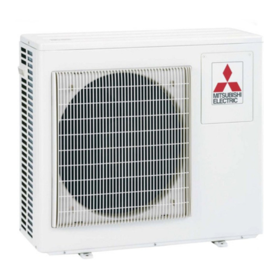
MXZ-3HA50VF
English is original.
Übersetzung des
Originals
Traduction du texte
d'origine
Vertaling van het
origineel
Traducción del
original
Traduzione
dell'originale
Μετάφραση του
αρχικού
Tradução do
original
Oversættelse af
den originale tekst
Översättning från
originalet
Orijinalin çevirisi
Оригиналът е текстът
на английски език.
Językiem oryginału
jest język angielski.
Originalspråket er
engelsk.
Installation Manual
• This manual only describes the installation of outdoor unit.
When installing the indoor unit, refer to the installation manual of indoor unit.
Installationsanleitung
• Diese Installationsanleitung gilt nur für die Installation des Außengerätes.
Zur Installation des Innengeräts siehe die Installationsanleitung für Innengeräte.
Notice d'installation
• Cette notice ne décrit que l'installation de l'appareil extérieur.
Lors de l'installation de l'appareil intérieur, consultez la notice d'installation de
cet appareil.
Installatiehandleiding
• Deze handleiding beschrijft alleen de installatie van de buitenunit.
Raadpleeg de installatiehandleiding van de binnenunit wanneer u deze
installeert.
Manual de instalación
• En este manual sólo se describe la instalación de la unidad exterior.
Para instalar la unidad interior, consulte el manual de instalación de dicha
unidad.
Manuale per l'installazione
• Questo manuale descrive solo l'installazione dell'unità esterna.
Per l'installazione dell'unità interna, fare riferimento al relativo manuale di
installazione.
Εγχειρίδιο εγκατάστασης
• Στο παρόν εγχειρίδιο περιγράφεται μόνο η εγκατάσταση της μονάδας εξωτερικού χώρου.
Για την εγκατάσταση της μονάδας εσωτερικού χώρου, ανατρέξτε στο εγχειρίδιο
εγκατάστασης της μονάδας εσωτερικού χώρου.
Manual de Instalação
• Este manual descreve apenas a instalação da unidade exterior.
Quando proceder à instalação da unidade interior, consulte o manual de instalação
da unidade interior.
Installationshåndbog
• Denne håndbog beskriver kun, hvordan udendørsenheden installeres.
Vedrørende installation af indendørsenheden henvises til installationshåndbogen
for indendørsenheden.
Installationsanvisning
• Denna installationsanvisning beskriver endast installation av utomhusenheten.
Se den separata installationsanvisningen för inomhusenheten.
Kurulum Kılavuzu
• Bu kılavuzda yalnızca dış ünitenin kurulumu açıklanmaktadır.
İç ünite kurulum işlemini yaparken iç ünite kurulum kılavuzuna bakın.
Ръководство за монтаж
• Това ръководство описва само монтажа на външното тяло.
При монтиране на вътрешното тяло вижте ръководството за монтаж на
вътрешното тяло.
Instrukcja montażu
• Niniejsza instrukcja zawiera tylko opis instalacji jednostki zewnętrznej.
W przypadku instalowania jednostki wewnętrznej należy odnieść się do instrukcji
montażu jednostki wewnętrznej.
Installasjonshåndbok
• Denne håndboken beskriver installasjonen av den utvendige enheten.
Når den innvendige enheten skal installeres, se installasjonshåndboken til den
innvendige enheten.
For INSTALLER
Für INSTALLATEUR
Destinée à l'INSTALLATEUR
Voor de INSTALLATEUR
Para el INSTALADOR
Per il TECNICO INSTALLATORE
Για τον ΤΕΧΝΙΚΟ
Para o INSTALADOR
Til INSTALLATØREN
För INSTALLATÖREN
TESİSATÇI İÇİN
За ИНСТАЛАТОРА
DLA INSTALATORA
For INSTALLATØR
English
Deutsch
Français
Nederlands
Español
Italiano
Ελληνικά
Português
Dansk
Svenska
Türkçe
Български
Polski
Norsk
Advertisement

Related Manuals for Mitsubishi Electric MXZ-3HA50VF


Summary of Contents for Mitsubishi Electric MXZ-3HA50VF
- Page 1 Split-type Air-Conditioner MXZ-3HA50VF Installation Manual For INSTALLER English is original. English • This manual only describes the installation of outdoor unit. When installing the indoor unit, refer to the installation manual of indoor unit. Installationsanleitung Für INSTALLATEUR Übersetzung des Deutsch • Diese Installationsanleitung gilt nur für die Installation des Außengerätes.
- Page 2 Manual Download http://www.mitsubishielectric.com/ldg/ibim/ EN Go to the above website to download manuals, select model name, then choose language. DE Besuchen Sie die oben stehende Website, um Anleitungen herunterzuladen, wählen Sie den Modellnamen und dann die Sprache aus. FR Rendez-vous sur le site Web ci-dessus pour télécharger les manuels, sélectionnez le nom de modèle puis choisissez la langue. NL Ga naar de bovenstaande website om handleidingen te downloaden, de modelnaam te selecteren en vervolgens de taal te kiezen.
-
Page 3: Table Of Contents
Required Tools for Installation CONTENTS Phillips screwdriver Flare tool for R32, R410A Level Gauge manifold for R32, R410A 1. BEFORE INSTALLATION ............1 Scale Vacuum pump for R32, R410A 2. OUTDOOR UNIT INSTALLATION ..........7 Utility knife or scissors Charge hose for R32, R410A 3. FLARING WORK AND PIPE CONNECTION ....... 8 Torque wrench Pipe cutter with reamer 4. PURGING PROCEDURES, LEAK TEST, AND TEST RUN ..9 Wrench (or spanner) 5. PUMPING DOWN ..............11 4 mm hexagonal wrench 1. BEFORE INSTALLATION MEANINGS OF SYMBOLS DISPLAYED ON INDOOR UNIT AND/OR OUTDOOR UNIT WARNING This unit uses a flammable refrigerant. - Page 4 Power Indoor/outdoor Max. height Frequency per indoor unit / for per indoor unit / for Cooling Heating Voltage capacity supply connecting wire difference *9 multi-system multi system 220-230- 3-core 4-core MXZ-3HA50VF 50 Hz 25 A 25 m / 50 m 15 m 25 / 50 46 dB (A) 50 dB (A) 240 V 2.5 mm 1.0/1.5 mm *1 Connect to the power switch which has a gap of 3 mm or more when open to interrupt the Factory-charged Maximum amount of Model source power phase. (When the power switch is shut off, it must interrupt all phases.) refrigerant charge refrigerant amount *2 Use wires in conformity with design 60245 IEC 57. Use the indoor/outdoor connecting wire MXZ-3HA50VF 1.6 kg...
- Page 5 FREE SPACE REQUIRED AROUND OUTDOOR UNIT Obstacles above Front (blowing) side open When there is no obstacle in front and As long as space indicated 100 or more on the sides of the unit, it is allowed in the figure is provided, it 200 or more to install the unit where an obstacle is is allowed to install the unit 500 or more above the unit only if the space shown where obstacles are behind...
- Page 6 1-4-1. Minimum installation area for Outdoor units If you unavoidably install a unit in a space where all four sides are blocked or there are depressions, confirm that one of these situations (A, B or C) is satisfied. Note: These countermeasures are for keeping safety not for specification guarantee. A) Secure sufficient installation space (minimum installation area Amin). Install in a space with an installation area of Amin or more, corresponding to refrigerant quantity M (factory-charged refrigerant + locally added refrigerant). M [kg] Amin [m²] Amin B) Install in a space with a depression height of [ 0.125 [m]. Height from the bottom of Height from the bottom of 0.125 [m] or less 0.125 [m] or less C) Create an appropriate ventilation open area. Make sure that the width of the open area is 0.9 [m] or more and the height of the open area is 0.15 [m] or more. However, the height from the bottom of the installation space to the bottom edge of the open area should be 0.125 [m] or less. Open area should be 75% or more opening. 75% or more opening Height H 0.15 [m] or more Width W 0.9 [m] or more Height from the bottom 0.125 [m] or less En-4...
- Page 7 1-4-2. Minimum installation area for Indoor units Install in a room with a floor area of Amin or more, corresponding to refrigerant quantity M (factory-charged refrigerant + locally added refrigerant). Install the indoor unit so that the height from the floor to the bottom of the indoor unit is h0; for wall mounted: 1.8 m or more; for ceiling suspended, cassette and ceiling concealed: 2.2 m or more. There are restrictions in installation height for each model, so read the installation manual for the particular unit. M [kg] Amin [m²] 15.5 h0 ] 1.8 [m] Wall mounted h0 ] 2.2 [m] h0 ] 2.2 [m] h0 ] 2.2 [m] Ceiling suspended Cassette Ceiling concealed En-5...
- Page 8 1-5. INSTALLATION DIAGRAM After the leak test, apply insulating material tightly so that there is no gap. Open as a rule More than 500 mm When the piping is to be attached to a wall containing metals (tin if the front and both plated) or metal netting, use a chemically treated wooden piece 20 sides are open mm or thicker between the wall and the piping or wrap 7 to 8 turns of insulation vinyl tape around the piping. To use existing piping, perform COOL operation for 30 minutes and pump down before removing the old air conditioner. Remake flare according to the dimension for new refrigerant. More than 100 mm More than 200 mm if there are obstacles to both sides WARNING More than 100 mm To avoid risk of fire, embed or protect the refrigerant piping. External damage on the refrigerant piping can be cause of fire.
-
Page 9: Outdoor Unit Installation
1-6. DRAIN PIPING FOR OUTDOOR UNIT Please perform the drain piping work only when draining from one place. 1) Choose one hole to discharge drain and install the drain socket (1) to the hole. 2) Close the rest of the holes with the drain caps (2). 3) Connect the soft PVC hose (L) of 15 mm in the inside diameter on the market with the drain socket (1) and lead drain. Note: Install the unit horizontally. Do not use the drain socket (1) and the drain caps (2) in the cold regions. Drain may freeze and it makes the fan stop. The outdoor unit produces condensate during the heating operation. Select the installation place to ensure to prevent the outdoor unit and/or the grounds from being wet by drain water or damaged by frozen drain water. 2. OUTDOOR UNIT INSTALLATION 2-1. CONNECTING WIRES FOR OUTDOOR UNIT 1) Remove the service panel. 2) Loosen terminal screw, and connect indoor/outdoor unit connecting wire (B) from Terminal block for power supply the indoor unit correctly on the terminal block. Be careful not to make mis-wiring. Fix the wire to the terminal block securely so that no part of its core is appeared, and no external force is conveyed to the connecting section of the terminal block. 3) Firmly tighten the terminal screws to prevent them from loosening. After tighten- ing, pull the wires lightly to confirm that they do not move. 4) Perform 2) and 3) for each indoor unit. 5) Connect power supply cord (A). 6) Fix indoor/outdoor unit connecting wire (B) and power supply cord (A) with the cable clamps. 7) Close the service panel securely. Make sure that 3-3. PIPE CONNECTION is completed. • After making connections between both power supply cord (A) and indoor/ Service panel outdoor unit connecting wire (B), be sure to fix both cable and wire with cable clamps. -
Page 10: Flaring Work And Pipe Connection
3. FLARING WORK AND PIPE CONNECTION 3-1. PRECAUTIONS FOR DEVICES THAT USE R32 REFRIGERANT • U se ester oil, ether oil, alkylbenzene oil (small amount) as the refrigeration oil applied to the flared sections. • U se C1220 copper phosphorus, for copper and copper alloy seamless pipes, to connect the refrigerant pipes. Use refrigerant pipes with the thicknesses specified in the table to the below. Make sure the insides of the pipes are clean and do not contain any harmful contaminants such as sulfuric compounds, oxidants, debris, or dust. Always apply no-oxidation brazing when brazing the pipes, otherwise, the compressor will be damaged. WARNING: When installing or relocating, or servicing the air conditioner, use only the specified refrigerant (R32) to charge the refrigerant lines. Do not mix it with any other refrigerant and do not allow air to remain in the lines. -
Page 11: Purging Procedures, Leak Test, And Test Run
4. PURGING PROCEDURES, LEAK TEST, AND TEST RUN 4-1. PURGING PROCEDURES AND LEAK TEST Compound pressure 1) Remove service port cap of stop valve on the side of the outdoor unit gauge (for R32, R410A) –0.101MPa Stop valve cap *4 to 5 turns gas pipe. (The stop valves are fully closed and covered in caps in (–760 mmHg) (Torque 21.5 to Pressure gauge their initial state.) 27.5 N•m, 220 (for R32, R410A) *Close 2) Connect gauge manifold valve and vacuum pump to service port of to 280 kgf•cm) Gauge manifold *Open stop valve on the gas pipe side of the outdoor unit. valve (for R32, 3) Run the vacuum pump. (Vacuumize for more than 15 minutes.) R410A) 4) Check the vacuum with gauge manifold valve, then close gauge Handle Handle High manifold valve, and stop the vacuum pump. Hexagonal wrench Charge hose (for 5) Leave as it is for one or two minutes. Make sure the pointer of gauge... - Page 12 4-4. LOCKING THE OPERATION MODE OF THE AIR CONDITIONER (COOL, DRY, HEAT) • Description of the function: With this function, once the operation mode is locked to either COOL/DRY mode or HEAT mode, the air conditioner operates in that mode only. * Changing the setting is required to activate this function. Please explain about this function to your customers and ask them whether they want to use it. [How to lock the operation mode] 1) Be sure to turn off the main power for the air conditioner before making the setting. 2) Set the “3” of SW1 on the outdoor controller board to ON to enable this function. SW871 3) To lock the operation mode in COOL/DRY mode, set the “4” of SW1 on the outdoor controller board to OFF. To lock the operation in HEAT mode, set the same switch to ON. 4) Turn on the main power for the air conditioner.
-
Page 13: Pumping Down
5. PUMPING DOWN When relocating or disposing of the air conditioner, pump down the system following the procedure below so that no refrigerant is released into the atmosphere. 1) Turn off the breaker. 2) Connect the gauge manifold valve to the service port of the stop valve on the gas pipe side of the outdoor unit. 3) Fully close the stop valve on the liquid pipe side of the outdoor unit. 4) Turn on the breaker. 5) Start the emergency COOL operation on all the indoor units. 6) When the pressure gauge shows 0.05 to 0 MPa [Gauge] (approx. 0.5 to 0 kgf/cm ), fully close the stop valve on the gas pipe side of the outdoor unit and stop the operation. (Refer to the indoor unit installation manual about the method for stopping the operation.) * If too much refrigerant has been added to the air conditioner system, the pressure may not drop to 0.05 MPa [Gauge] (approx. 0.5 kgf/cm ), or the protection function may operate due to the pressure increase in the high-pressure refrigerant circuit. If this occurs, use a refrigerant collecting device to collect all of the refrigerant in the system, and then recharge the system with the correct amount of refrigerant after the indoor and outdoor units have been relocated. 7) Turn off the breaker. Remove the pressure gauge and the refrigerant piping. WARNING When pumping down the refrigerant, stop the compressor before disconnecting the refrigerant pipes. The compressor may burst and cause injury if any foreign substance, such as air, enters the pipes. En-11... - Page 14 CONDITION of indoor units. 35/24 °C 7/6 °C OUTDOOR DB/WB Manufacturer : MITSUBISHI ELECTRIC CONSUMER PRODUCTS (THAILAND) CO., LTD. 700/406 MOO 7, TAMBON DON HUA ROH, AMPHUR MUANG, CHONBURI 20000, THAILAND YEAR OF MANUFACTURE SERIAL NO. 0035 MADE IN THAILAND...
- Page 15 EG-DEKLARATION OM ÖVERENSSTÄMMELSE KUUTUS MITSUBISHI ELECTRIC CONSUMER PRODUCTS (THAILAND) CO., LTD 700/406 MOO 7, TAMBON DON HUA ROH, AMPHUR MUANG, CHONBURI 20000, THAILAND hereby declares under its sole responsibility that the air conditioners and heat pumps described below for use in residential, commercial and light-industrial environments: erklärt hiermit auf seine alleinige Verantwortung, dass die Klimaanlagen und Wärmepumpen für das häusliche, kommerzielle und leicht-industrielle Umfeld wie unten beschrieben:...
- Page 16 Importer: Mitsubishi Electric Europe B.V. Capronilaan 46, 1119 NS, Schiphol Rijk, The Netherlands French Branch 25, Boulevard des Bouvets, 92741 Nanterre Cedex, France German Branch Mitsubishi-Electric-Platz 1, 40882 Ratingen, Germany Belgian Branch Autobaan 2, 8210 Loppem, Belgium Irish Branch Westgate Business Park, Ballymount, Dublin 24, Ireland...
Need help?
Do you have a question about the MXZ-3HA50VF and is the answer not in the manual?
Questions and answers