Table of Contents
Advertisement
Quick Links
Advertisement
Table of Contents

Subscribe to Our Youtube Channel
Related Manuals for ahlmann AS 150


Summary of Contents for ahlmann AS 150
- Page 1 OPERATING INSTRUCTIONS SWING SHOVEL LOADER 1000995A AS 150 Ahlmann Baumaschinen GmbH Am Friedrichsbrunnen 2 D-24782 Büdelsdorf Telefon 04331/351-325 Internet: www.ahlmann-baumaschinen.de Telefax 04331/351404 E-Mail: info@ahlmann-baumaschinen.de...
- Page 2 Introduction Preface Ahlmann swing loaders, articulated loaders and front loaders are part of Ahlmann selection of heavy construction equipment, and design for a wide range of uses. Years of experience in manufacturing earth-moving equipment and various auxilliary tools, modern construction and manufacturing approaches, careful testing and an stringent quality control assure the reliability of your Ahlmann wheel loader.
- Page 3 Table of Contents Abbreviations used = Safety at work regulations = Road safety regulations Version: 02.2007 Printed: 02.2007 S150/S151/S152/Z152...
-
Page 4: Table Of Contents
Table of Contents Table of Contents Basic Safety Notes Warnings and symbols ......................1 - Appropriate use ........................1 - Administrative tasks ........................ 1 - Selecting and training staff ...................... 1 - Safety notes in various operating modes .................. 1 - 1.5.1 Normal operations ........................ - Page 5 Table of Contents 5.2.5 Heating and ventilation system/Air conditioning unit(SA) ............5 - 5.2.5.1 Blower output ........................... 5 - 5.2.5.2 Turning on the heating ......................5 - 5.2.5.3 Turning on the air conditioning unit (SA) ................. 5 - 5.2.5.4 Setting the temperature ......................5 - De-commissioning ........................
- Page 6 Elektrical wiring diagram ......................10 - 10.2 Hydraulic diagram ........................10 - 10.2.1 Hydraulik-Schaltplan AS 150 (Bolzenverriegelung) Ausführung "20 km/h" und "25 km/h" ..10 - 10.2.2 Hydraulik-Schaltplan AS 150 (Bolzenverriegelung) Ausführung "40 km/h" ......10 - 10.2.3 Hydraulik-Schaltplan AS 150 (Klauenverriegelung) Ausführung "20 km/h" ......10 - 10.2.4...
- Page 7 Safety regulations...
-
Page 8: Warnings And Symbols
Safety regulations Fundamental safety instruction Warnings and symbols In this operation manual the following designations or symbols are used for important information. NOTE Special information for the economical use of the machine. CAUTION Special information for necessities and prohibi- tions for avoiding damages. DANGER Information or necessities and prohibitions for prevention of damage to persons or extensive... - Page 9 Safety regulations 1.3.2 In addition to the operating manual (machine and engine) the general applicable and other binding regula- tions for the prevention of accidents (especially the safety regulations of the German Trade Association - VBG 40) as well as the regulations for environment protection must be observed and the personnel must be accordingly instructed.
-
Page 10: Normal Operations
Safety regulations These persons must: - have attained the age of 18 years, - be physically and intellectually suitable, - have been instructed in the operation or maintenance of the machine and must have demonstrated their ability to their employer, - must be expected to carry out the work conveyed to them in diligent manner. - Page 11 Safety regulations 1.5.1.9 Avoid any work operation which appears to be dangerous! 1.5.1.10 Persons must not be carried in the working equipment, e.g.in the attachments! 1.5.1.11 The operator may only carry out work with the machine when no persons are in the danger zone. The danger zone means that area near the machine where persons may be injured - by work-induced movements of the machine,...
- Page 12 Safety regulations 1.5.1.21 The person giving guidance must be a reliable person and must be informed about his tasks before commencement of the work. 1.5.1.22 The driver and guide must agree on signals for communication. These signals may only be given by the driver and guide.
- Page 13 Safety regulations 1.5.1.34 During work-brakes and after work hours the driver should endeavor to leave the machine on good bearing soil and if possible on level ground and safeguard the machine to prevent it from unintentionally rolling away. 1.5.2 Special work within the exploitation of the machine and elimination of defects during process or work;...
- Page 14 Safety regulations 1.5.2.9 Only experienced personnel should be entrusted with the securing of loads! Loads must be secured so that they cannot slip or fall down. 1.5.2.10 Attached loads may only be moved with the machine when the road is graded. 1.5.2.11 When working with hoisting equipment/elevators the slingers may only work with the approval of the driver and from the side of the boom.
- Page 15 Safety regulations 1.5.2.22 Make sure that fuel, accessory material and interchanged parts are safely disposed of with no danger to the environment. 1.5.2.23 The machine should be checked by a specialist before commissioning. In addition, it should be checked after essential modifications before it returns to service. 1.5.2.24 The machine must be checked by a specialist once a year.
-
Page 16: Hydraulics
Safety regulations 1.6.1.3 In the case of sparking over any work or move- ment must stop. Instructions to be followed: bring the machine out of the danger area by lifting or lowering the attachments or by swiveling away or driving the machine out of the area. -
Page 17: Gas, Dust, Steam, Smoke
Safety regulations 1.6.4 Oil, grease and other chemical substances 1.6.4.1 The relevant safety regulations must be observed when using oil, grease or other chemical substances. 1.6.4.2 Caution when working with hot fuel and other accessory material (danger of burning and scalding). 1.6.4.3 Caution when working with brake fluid and battery acid. - Page 18 Safety regulations 1.7.4 When the machine is loaded and transported the necessary auxiliary equipment must be fitted to prevent any unintended movement. The tires must be kept clean of mud, snow and ice so that the machine can drive on the ramp without danger of sliding.
-
Page 19: Signs
Signs... - Page 20 Bei angebautem Staplervor- "0"-Stellung schalten. ket cushioning mechanism satz oder Lasthaken darf die before fitting a fork-lift or Hubwerksfederung nicht ein- lifting hook. geschaltet werden. AS 150 17.5 - 3,0 bar 17.5 R 25 550/65 R 25 2.2 2.2 bar Baumaschinen GmbH...
- Page 21 Signs Symbol: Dangerous area, keep clear Sign: ATTENTION! Only the rear-wheel steering may be used for driving on public roads!! Sign: ATTENTION! - Steering is only available while the engine is running! Sign: » for slow-runners only « ATTENTION! The transfergear shift can only be operated while the vehicle is stationary. When changing gear, apply the service brakes and select neutral gear ("0").
- Page 22 Anti-Theft Protection...
- Page 23 To allow the authorities (such as the police, or customs and excise) to discover and identify stolen vehicles more quickly, Ahlmann construction machines are fitted with the following identification marks: Equipment ID marks (1) The machine type plaque (3-1/arrow). Amongst other details this includes the 17 digit FIN number (vehicle identification number) which starts with W09.
-
Page 24: Transponder Immobilizer
Anti-Theft Protection (12) Push steering column headlamp switch to select "beam" (4-5/5). * (13) Lock both doors. (14) Lock engine hood. (15) Lock fuel tank filler cap. * If the vehicle is short-circuited, bystanders will be alerted by the unusual lighting displayed. Transponder Immobilizer (Optional) The "Transponder Immoblizer"... -
Page 25: Description
Description... -
Page 26: Overview
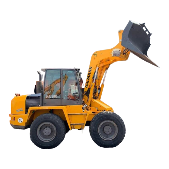
Constructional and design enhancements are important for the technical development of this equipment and may lead to deviations between figures and content in this manual. These changes are summarized in Chapter 13. Please refer to Chapter 13 for details. Overview AS 150 Fig. 4-1 1 - Bucket protector 2 - Bucket/Attachment... -
Page 27: Accoustic Warning
Description Swivel assembly and Axle support The twin rotational cylinders are driven by a separate gear oil pump via a control valve. The swivel assembly is attached to the cylinders via drive chains, and thus totally free of play. Rotation can occur simutaneously while lifting the boom without any interference between the two components. -
Page 28: Air-Conditioning
Description Air Conditioning (optional) The loader is equipped with an air conditioning unit that allows the driver to set the desired temperature, thus guaranteeing improved operator response and considerably enhancing operator concentration. At the same time, the air conditioning unit dehydrates the air entering the cab, preventing condensation and steamed up windows, and allowing for better visibility. -
Page 29: Bucket Cushioning
Description Bucket Cushioning When driving the loader over a longer distance, particularly if the bucket is loaded, it makes sense to engange the bucket cushioning feature (4-8/15) to prevent the loader from seesawing. This particularly applies on uneven terrain and if the loader is driven at higher speeds. ATTENTION Bucket cushioning can only be activated while moving the loader, but not for normal... - Page 30 Description (4) Changing a front wheel: - Lift and mechanically prop up bucket arm [e.g. by inserting the bucket arm support (option) (1-1/arrow)] and lower bucket arm until it rests on the bucket arm support. - Block the swivel assembly. To do so remove the wedge (1-3/arrow) from the holder, insert it in the swivel retainer (1-4/arrow) and use a spring-pin to lock it in this position .
- Page 31 Description 4.10 Operating elements 1 - Locking device for steering column adjustment - forwards/backwards - axially parallel to steering column 2 - Throttle 3 - Double pedal for service brakes/inching 4 - Foot pedal for swivel 5 - Steering column switch - forwards: right indicator - backwards:...
-
Page 32: Dashboard
Description 4.11 Dashboard 11 12 13 14 15 23 22 21 20 Fig. 4-8 1 - Rocker switch for permanently engaging auxiliary hydraulics (opt.) Warning Indicator Unit: 2 - not used 3 - not used 4 - Push-button for speed select (nur für Langsamläufer) 5 - Rocker switch for differential lock (opt.) 6 - Fuel indicator 7 - Cooling water temperature display/... - Page 33 Description Fuse box (Item 17): 1 Driving operations 7,5 A 2 Indicators 7,5 A 3 Hydraulics 10,0 A 4 Heating/Air cond. 10,0 A 5 Heated rear screen 15,0 A 6 Headlight beam 7,5 A 7 Headlight dip 7,5 A 8 Tail light left, Sidelight left 5,0 A 9 Tail light right, Sidelight right 5,0 A...
-
Page 34: Operations
Operations... -
Page 35: Checks Before You Start
Operations Operations The manufacturer reserves the right to alter construction details, which may lead to some deviations between your actual equipment and the figures shown in this manual, but will not affect the accuracy of the contents. Changes have been collated and documented in Chapter 13. -
Page 36: Fuel
Operations NOTE If the engine fails to fire after two attempts, follow the troubleshooting procedures outlined in the engine manual. In case of extremely low ambient temperature, follow the procedures outlined in the engine manual. After cold starting the blockwage warning indicator may light up, however, the indicator will be switched off as the hydraulic oil reaches normal temperature. -
Page 37: Driving On Public Roads
Operations 5.2.2.2 Oil Change Engine Refer to the operating manual for the engine and the operating manual for the equipment (section 8.2.6). 5.2.2.3 Oil Change Hydraulic System ATTENTION The viscosity of the hydraulic oil changes according to the temperature; therefore, the ambient temperature in the place where the machine will be used determines what viscosity class (SAE class) must be chosen. - Page 38 Operations Before entering a public road ensure that the following safety checks have been performed: 5.2.3.1 Transporting a bucket (1) Lower the bucket arm until the lowest point of the bucket arm or the bucket heel is at least 30 cm above the road (5-4).
-
Page 39: Slow-Runner Type "20 Km/H" And "25 Km/H
Operations 5.2.4 Working with the loader 5.2.4.1 Slow-runner type "20 km/h" and "25 km/h" DANGER Always fasten your seat belt while working with a swivel loader. Normally, all work is executed in hydraulic drive stage "II" (4-7/1) and a transmission step (4-8/4) that matches the working conditions. - Page 40 Operations (1) Close both doors. (2) Release the parking brake (4-7/4). (3) Pre-select a gear [(4-8/4) » applies to slow-runners type "20 km/h" and "25 km/h" «] or [(4-7/1) » applies to fast- runners type "40 km/h" «]. (4) Pre-select a hydraulic drive step [(4-7/1) » applies to slow-runners type "20 km/h"...
- Page 41 Operations 5.2.5 Heating and Ventilation Unit / Air- Conditioning (opt.) 5.2.5.1 Adjusting the airflow (1) Turn the rotary switch (5-6/4) for the fan to position 0, 1 or 2, depending on the amount of air desired. (2) Adjust the direction of the air flow by means of the lateral nozzles on the left and right sides (5-7/1 and 5-8/1).
-
Page 42: Switching Off The Diesel Engine
Operations Stopping loader operations 5.3.1 Parking the loader (1) Stop the vehicle on firm and preferably level ground. (2) Apply the parking brake (4-7/4). (3) Lower the bucket or front-loaded attachment to the ground. (4) Set the drive switch (4-7/3) to “0”. DANGER If parking on a slope or gradient cannot be avoided, wheel chocks must be used and placed... -
Page 43: Isri Seat
Operations Adjusting the driver´s seat 5.4.1 Isri seat (1) Use the lever (5-9/2) to adjust the inclination of the backrest or fold the backrest. (2) Pull the lever (5-9/3) up to adjust the height and tilt for the rear of the seat. (3) Pull (5-9/4) up adjust the height and tilt for the front of the seat. - Page 44 Operations (2) Height adjustment: The height can be adjusted in several steps. Lift the driver’s seat to the desired height until it can be heard to engage. The seat returns to the lowest position when it is lifted over the topmost position (stop) (5-12). Fig.
- Page 45 Operations (5) Adjusting the backrest: Use the locking lever (5-15/arrow) to adjust the backrest. NOTE The locking lever must engage in the desired position. It must be impossible to move the backrest to another position when the lever has engaged. Fig.
- Page 46 Attachments...
- Page 47 Attachments Attachments Coupling and uncoupling attach- ments without hydraulics 6.1.1 Standard/Light Material Bucket Coupling (1) Lower the loader arms as far and possible and tilt the quick coupler. (2) Drive the loader up to the bucket (6-1). (3) Pick up the bucket using the quick coupler frame and, by simultaneously tilting the quick coupler, raise the Fig.
-
Page 48: Fork-Lift Attachment
Attachments 6.1.2 Fork-lift attachment NOTE Fig. 6-4 shows the vehicle with with the fork- lift attachment at full stretch. For coupling and uncoupling procedures please refer to the description of the standard/ light material bucket in section 6.1.1. DANGER The lock pins of the quick coupler must be inserted in the lifting holes on both sides of fork-lift attachment and must protude visibly when viewed from the side (6-5/arrow). -
Page 49: Lifting Hook
Attachments 6.1.3 Lifting Hook NOTE For coupling and uncoupling procedures please refer to the description of the standard/ light material bucket in section 6.1.1. The type plate is on the top right of the lifting hook coupler frame. DANGER The lock pins of the quick coupler must be inserted in the lifting holes on both sides of fork-lift attachment and must protude visibly when viewed from the side . - Page 50 Attachments (5) Check seating and ensure that the pins are locked left and right. DANGER The lock pins of the quick coupler must be inserted in the lifting holes on both sides of bucket and must protude visibly when viewed from the side (6-9/arrow).
- Page 51 Attachments Notes on using the multi-purpose bucket The multi-purpose bucket can be used for: - blading (6-13) Fig. 6-13 - clamming (6-14) Fig. 6-14 - grappling (6-15) and for - digging like a normal bucket. Fig. 6-15 S150/S151/S152/Z152...
-
Page 52: Front-End Excavator
Attachments 6.2.2 Front-end excavator Coupling For coupling and uncoupling procedures please refer to the description of the multi-purpose bucket in section 6.2.1 (1) ...(10), except that all four hydraulic hose sleeves on the front-end excavator need to be attached to the connectors on the quick coupler assembly. -
Page 53: Using Other Attachments
Attachments 6.2.2.1 Changing a bucket (1) Lift and mechanically prop up bucket arm [e.g. by inserting the bucket arm support (option) (1-1/arrow)] and lower bucket arm until it rests on the bucket arm support. (2) Move the front-end loader into a position where the bucket heel is flush with the ground. -
Page 54: Rescue, Towing, Lashing, Lifting By Crane
Rescue, Towing, Lashing, Crane-Lifting... -
Page 55: Rescue, Towing, Lashing
Rescue, Towing, Lashing, Crane-Lifting Rescue, Towing, Lashing, Crane-Lifting Rescue, Towing, Lashing 7.1.1 Rescue/Towing of the swing loader in case of engine or transmission failure DANGER On public roads, first secure the rescue area. ATTENTION Do not attempt to tow-start the swivel loader. Any attempt to do so will cause damage. - Page 56 Rescue, Towing, Lashing, Crane-Lifting (4) Align the wheels on the front axle and then use the steering selector lever (4-6/4) to set the steering mode to "rear-wheel-steering". (5) Release the parking brake (4-7/4). (6) Apply the bucket protector to protect the lip and teeth of the bucket (5-4/arrow).
- Page 57 Rescue, Towing, Lashing, Crane-Lifting (15) Detach the spring brake. To do so, loosen the counter nuts (7-4/2 and 7-4/4) and set screws (7-4/1 and 7-4/3) a quarter turn in sequence. One turn is required to slacken the spring brake. ATTENTION Do not exceed one turn! Tighten the set screws in sequence.
-
Page 58: Towing The Swivel Loader In Case Of Transmission Failure
Rescue, Towing, Lashing, Crane-Lifting DANGER - In case of engine failure considerably more force is required to steer the vehicle. - Tow the vehicle at slow speed (2 km/h). - For longer towing distances, the defective vehicle should be loaded (see 7-2/1 and 7-2/2, 7-3/1 and 7-3/2) for lashing points. - Page 59 Rescue, Towing, Lashing, Crane-Lifting (13) Detach the spring brake. To do so, loosen the counter nuts (7-4/2 and 7-4/4) and set screws (7-4/1 and 7-4/3) a quarter turn in sequence. One turn is required to slacken the spring brake. ATTENTION Do not exceed one turn! Tighten the set screws in sequence.
- Page 60 Rescue, Towing, Lashing, Crane-Lifting For longer towing distances, the defective vehicle should be loaded (see 7-2/1 and 7-2/2, 7-3/1 and 7-3/2) for lashing points. The max. permissible load of the front towing and shunting coupling (7-2/1) is 8.0 t horizontally and axially. The max.
-
Page 61: Maintenance
Maintenance... - Page 62 Maintenance (Maintenance Plan AS 150 Type 40 km/h) Intervals in working hours max. permissible intervals, 12.2 12.1 11.2 12.1 8.1/8.2/8.3/8.4 4184997A can be shorter dep. on use Maintenance Points 1.1/1.2/1.3/1.4/1.5 Engine Maintenance according to manufacturers specs Dry air filter unit: Check service display Change filter element if display shows red 12.1...
- Page 63 Maintenance (Maintenance Plan AS 150 Type 20 km/h und 25 km/h) Intervals in working hours max. permissible intervals, 4184996A 12.2 12.1 11.2 12.1 8.1/8.2/8.3/8.4 can be shorter dep. on use Maintenance Points 1.1/1.2/1.3/1.4/1.5 Motor Maintenance according to manufacturers specs Dry air filter unit: Check service display...
-
Page 64: Maintenance Notes
Maintenance Maintenance Constructional and design enhancements are important for the technical development of this equipment and may lead to deviations between figures and content in this manual. These changes are summarized in Chapter 13. Please refer to Chapter 13 for details.n. Maintenance Notes DANGER Ensure that the engine has stopped. -
Page 65: Maintenance Tasks
Maintenance Maintenance Tasks 8.2.1 Check engine oil fill-level See the operating manual for the engine. Fig. 8-1 8.2.2 Check axle oil fill-level 8.2.2.1 Rear axle (1) Remove the plugs from the axle arches (8-1/arrow) and/or (8-2/arrow). NOTE The oil level must reach the plug bore. Collect any escaping oil. -
Page 66: Front Axle
Maintenance 8.2.2.3 Front axle (1) Remove the plugs from the axle arches (8-4/arrow) and/or (8-5/arrow). NOTE The oil level must reach the plug bore. Collect any escaping oil. (2) Re-insert the plug. Fig. 8-4 Fig. 8-5 8.2.3 Check oil fill-level transfer gearbox »... - Page 67 Maintenance 8.2.4 Check oil fill-level transfer gearbox » Fast-runner 40 km/h « (1) Check oil-level in inspection glass (8-7/1). NOTE The oil level must be visible in the upper quarter of the inspection glass. If required use the plug bore to top up with transmission oil (8-7/2).
-
Page 68: Rear Axle
Maintenance 8.2.6 Change the engine oil (1) Remove the inspection plate from the engine trough (8-10/Pfeil). (2) Place a sufficiently large oil spill tray under the motor oil sump. (3) Open the engine hood. (4) Remove the inspection plate for the engine oil drain plug. -
Page 69: Planetary Gear
Maintenance NOTE Refer to the maintenance plan (pages 8-1and 8-2) for details on required amounts. The oil fill-level will drop after a few minutes. Top up with oil, until the required level has been reached and remains constant. The axle vent valve (8-13/arrow) must be free of contamination. -
Page 70: Front Axle
Maintenance 8.2.7.3 Front axle (1) Place a sufficiently large oil spill tray underneath the vehicle. (2) Remove plugs from axle arches (8-16/1, 8-16/2, 8-16/3, 8-16/4, and 8-17/Pfeil) and drain oil. ATTENTION Dispose of waste oil in an environmentally friendly way! Fig. - Page 71 Maintenance 8.2.8 Oil change transfer gear gox » slow-runners 20 km/h and 25 km/h « (1) Place a sufficiently large oil spill tray under the transfer case. (2) Remove plugs (8-19/1 and 8-19/2) and allow oil to drain. ATTENTION Dispose of waste oil in an environmentally friendly way! (3) Re-insert plugs (8-19/1).
-
Page 72: Oil Change Hydraulics System
Maintenance 8.2.10 Oil change hydraulics (1) Open the engine hood. (2) Ensure that an oil spill tray is available (for size refer to section Kapitel 11.11). (3) Remove the inspection plate for the oil drain plug (8-22/arrow). (4) Attach the drainage nozzle with hose from the tool case (4-1/13) to the oil drain plug. - Page 73 Maintenance 8.2.11 Changing the suction return filter insert ATTENTION Change the filter insert at the intervals indicated in the maintenance plan or when clogging is indicated (4-8/34). NOTE When cold starting the vehicle the clogging indicator may light up prematurely. The indicator will go off as soon as the hydraulic oil warms up.
-
Page 74: Changing The Safety Cartridge
Maintenance 8.2.12 Servicing/Changing the airfilter NOTE The filter insert requires attention when the maintenance indicator (8-28/1) shows red, or after 12 months, which ever is sooner. (1) Open the engine hood. (2) Unscrew both wing screws on the top of the mainte- nance grid (8-28/2). -
Page 75: Changing The Fuel Filter
Maintenance (1) Remove the filter cartridge (section 8.2.12). (2) Pierce the seal of the safety cartridge (8-30/arrow) from the inside by using a screwdriver or similar tool and pull up both strips. (3) Hold the filter cartridge by both strips and pull it out by carefully turning it back and forth. - Page 76 Maintenance 8.2.16 Servicing/Changing the fresh air filter (1) Lift and mechanically prop up bucket arm [e.g. by inserting the bucket arm support (option) (1-1/arrow)], Lower bucket arm until it rests on the bucket arm support and swivel all the way to the right or left. (2) Loosen and remove the four holding screws (8-33/ arrows) of the heating unit cover, and then remove the cover.
-
Page 77: Greasing Points
Maintenance Greasing points NOTE Greasing points are painted red on the vehicle. 8.3.1 Rear axle pivot bolt (8-36/arrows) ATTENTION The rear axle pivot bolt must be greased every 10 operating hours. Fig. 8-36 8.3.2 Rear axle (8-37/arrows) ATTENTION The rear axle spindle bolts must be greased every 50 operating hours. -
Page 78: Cab Doors
Maintenance 8.3.4 Swivel assembly (8-39/arrows) The grease pack is designed to avoid friction, to seal the unit and protect it from corrosion. For this reason, the bearings should be greased liberally every 10 operating hours until grease emerges. When greasing the swivel assembly rotate the loader arm in 20°... -
Page 79: Engine Hood
Maintenance 8.3.7 Engine hood ATTENTION The hinges of the engine hood (8-42/arrows) must be lubricated every 50 operating hours. Fig. 8-42 Oiling points 8.4.1 Support valve control mechanism ATTENTION The support valve control mechanism must be oiled with engine oil every 50 operating hours. (1) Raise the loader arm, insert the loader arm support and swivel the arm out fully to the left or right. - Page 80 Troubleshooting...
- Page 81 Troubleshooting Troubleshooting NOTE *) These tasks to be performed by authorized staff only Malfunction Probable Cause Remedy Engine Refer to engine manual Engine will not start Drive selector (4-7/3) not in Put drive selector in neutral neutral Loader arm cannot be lifted or Pressure valve in in control valve Remove pressure valve, clean and dropped...
- Page 82 Troubleshooting Malfunction Probable Cause Remedy Malfunction in travel and main Filter clogged Change filter inserts hydraulics Low oil fill-level in hydraulic oil Top up with oil reservoir Electrical connection of axial Connect according to wiring piston pump not tight, separated diagram or clean or corroded High pressure valves...
- Page 83 Wiring and Hydraulics...
- Page 84 1 - 3 Elektrisk kopplingsschema 10.1 - 02.2003 Elektrik-Schaltplan/Schéma électrique/Wiring diagramm/Elektrisch schakelschema/ 9 10 15 16 17 18 23/16 23/17 23/6 23/11 23/5 TS1 DS2 10-1 S150/S151/S152/Z152...
- Page 85 2 - 3 Elektrisk kopplingsschema 10.1 - 02.2003 Elektrik-Schaltplan/Schéma électrique/Wiring diagramm/Elektrisch schakelschema/ S150/S151/S152/Z152 10-2...
- Page 86 3 - 3 Elektrisk kopplingsschema 10.1 - 02.2003 Elektrik-Schaltplan/Schéma électrique/Wiring diagramm/Elektrisch schakelschema/ 100 101 10-3 S150/S151/S152/Z152...
-
Page 87: Wiring Diagrams
Wiring and Hydraulics 10 10.1 Wiring Diagram Pos. Name Starter button Relay: Starter cut-out Fuel fill-level display Cooling water temperature display Tachometer Operating hour counter Actuator: Working floodlights Fuse (Chapter 4.9 Pos. 17/13) Fuse (Chapter 4.9 Pos. 17/6) Fuse (Chapter 4.9 Pos. 17/7) Actuator: StVZO-Beleuchtung Indicator pick-up Actuator: Hazard Warning Lights... - Page 88 10 Wiring and Hydraulics Pos. Name Diode combination (only fast-runners) Pulse generator indicator light unit gear selector Relay gear selector (only fast-runners) Relay gear selector (only fast-runners) Brücke gear selector (only Langsamläufer) Relay gear selector (only fast-runners) Relay gear selector (only fast-runners) Relay gear selector (only fast-runners) Relay gear shift switch Relay 1st gear...
- Page 89 Wiring and Hydraulics 10 Pos. Name Interval pick-up Fuse (Chapter 4.9 Pos. 17/11) Acuator interval wipers front Acuator screen washer front Acuator wiper/washer back Acuator rear screen heating Fuse (Chapter 4.9 Pos. 17/5) MaxiFuse (40 A) Fuse (Chapter 4.9 Pos. 17/4) Socket dashboard 2 pin Fuse (Chapter 4.9 Pos.
- Page 90 Hydraulics Diagram AS 150 (bolt lock) Type "20 km/h" and "25 km/h" 10.2.1 - 04.2001 Anschluss an Pilot- druck Auskippen Anschluss an Pilotdruck Senken Anschluss an Speisedruck Fahrtrichtung Y1/B4/rot X2/A3/grün X1/A4/blau X1/A2/schwarz 20 bar Y8 Y9 Einschaltdruck120 bar Abschaltdruck 150 bar Gauge part _ ..
- Page 91 Hydraulics Diagram AS 150 (bolt lock) Type "40 km/h" 10.2.2 - 04.2001 Anschluss an Pilot- druck Auskippen Anschluss an Pilotdruck Senken Anschluss an Speisedruck Einschaltdruck 120 bar Abschaltdruck 150 bar Gauge part _ .. _ .. Optional equipment 10-5 S150/S151/S152/Z152...
- Page 92 Hydraulics Diagram AS 150 (claw lock) Type "20 km/h" 10.2.3 - 01.2006 NS58 NS55 NS51 G1/2 G1/2 NS52 G1/2 G1/2 G1/2 G1/2 3/4"-16UNF 3/4"-16UNF G1/2 G1/2 G1/2 G1/2 G3/8" G3/8" G1/2 G1/2 Anschluß an Pilotdruck Auskippen NS53 0,7 l NS54 G3/8"...
- Page 93 Hydraulics Diagram AS 150 (claw lock) Type "40 km/h" 10.2.4 - 01.2006 NS58 NS55 NS51 G1/2 G1/2 NS52 G1/2 G1/2 G1/2 G1/2 3/4"-16UNF 3/4"-16UNF G1/2 G1/2 G1/2 G1/2 G3/8" G3/8" G1/2 G1/2 Anschluß an Pilotdruck Auskippen NS53 NS54 0,7 l G3/8"...
-
Page 94: Hydraulic Diagram
Wiring and Hydraulics 10 10.2 Hydraulics Diagram 10.2.1 Hydraulics Diagram AS 150 (bolt lock) Type "20 km/h" and "25 km/h" Pos. Name Swivel cylinder DW 100/45/785/1095 Actuator support Leak free lock Support cylinder EW 60/210/518 Storage facility pipe burst protection (opt.) - Page 95 Wiring and Hydraulics 10 10.2.2 Hydraulics Diagram AS 150 (bolt lock) Type "40 km/h" Pos. Name Swivel cylinder DW 100/45/785/1095 Actuator support Leak free lock Support cylinder EW 60/210/518 Storage facility pipe burst protection (opt.) Locking cylinder DW 80/60/377 Auxiliary hydraulics right circuit...
- Page 96 Wiring and Hydraulics 10 10.2.3 Hydraulics Diagram AS 150 (claw lock) Type "20 km/h" Pos. Name Swivel cylinder DW 100/45/785/1095 Actuator support Leak free lock Support cylinder EW 60/210/518 Storage facility pipe burst protection (opt.) Auxiliary hydraulics right circuit Locking cylinder GDW 63/40/70/382...
- Page 97 Wiring and Hydraulics 10 10.2.4 Hydraulics Diagram AS 150 (claw lock) Type "40 km/h" Pos. Name Swivel cylinder DW 100/45/785/1095 Actuator support Leak free lock Support cylinder EW 60/210/518 Storage facility pipe burst protection (opt.) Auxiliary hydraulics right circuit Locking cylinder GDW 63/40/70/382...
- Page 98 Technical Data (Equipment)
-
Page 99: Equipment
11 Technical Data (Equipment) Technical Data (Equipment) NOTE The technical data assume 17.5-25 12 PR tire specs. 11.1 Equipment - Height 3100 mm - Width 2460 mm - Wheelbase 2200 mm - Track 1980 mm - Operating weight without attachments 10455 kg - Clearance - Differential... -
Page 100: Axle Loads
Technical Data (Equipment) 11 Type " 25 km/h" 1st gear - Step I 0..5 km/h - Step II 0 ...10,5 km/h 2nd gear - Step I 0..11,5 km/h - Step II 0..25 km/h Type " 40 km/h" Alpha max. (Turtle symbol) 0..5 km/h 1st gear 0..11,5 km/h... -
Page 101: Fuel Supply System
11 Technical Data (Equipment) 11.11 Hydraulic subsystem - Volume 160 l - Hydraulic oil reservoir 115 l 11.11.1 Main hydraulics - Output flow pump I (priority valve controlled) 87 l/min - Output flow pump II (via swivel assembly and accumulator valve) 38 l/min - Total flow output 125 l/min... -
Page 102: Options
Technical Data (Equipment) 11 11.16 Oil Cooler (Combi-Cooler) with Thermostatically Controlled Valve - Capacity max. 30 kW - Throughflow 43 l/min 11.17 Noise Emission Type "20 km/h" Noise level (L Noise external: 106 dB(A) In-band accoustic level (L Noise level in cab: 81 dB(A) Type "25 km/h"... - Page 103 Technical Data (Attachments)
-
Page 104: Buckets
12 Technical Data (Attachments) Attachments Notes The technical data assume 17.5-25 12 PR tires 12.1 Buckets Dimensions corresponding to ISO 7131/35 12-2 S150/S151/S152/Z152... - Page 105 Technical Data (Attachments) 12 12.1 Buckets Bucket type Bucket I Bucket II Bucket III Muliti-purpose with teeth no teeth no teeth bucket Bucket volume to DIN/ISO 7546 m³ 1,45 2,00 2,40 1,30 - heaped m³ 1,60 2,20 2,65 1,45 Bucket width 2480 2480 2480...
-
Page 106: Fork-Lift Attachment
12 Technical Data (Attachments) 12.2 Fork-lift attachment Measurements corresponding to ISO 7131/35 12-4 S150/S151/S152/Z152... - Page 107 Technical Data (Attachments) 12 12.2 Fork-lift Attachment Tine lenght 1200 mm Tine height 50 mm Distance between tines (from center) - min. 340 mm - max. 1340 mm Weight 310 kg Max. permissible load N according to DIN 24094 frontal - even ground (stability factor 1,25) 4025 kg - uneven groung (stability factor 1,67)
- Page 108 12 Technical Data (Attachments) 12.3 Front-end Loader Measurements according to ISO 7131/35 12-6 S150/S151/S152/Z152...
- Page 109 Technical Data (Attachments) 12 12.3 Front-end loader Breakout force at cutting edge of bucket max. 3720 daN Curling force at cutting edge of bucket max. 2830 daN Bucket volume Bucket width Net weight to DIN ISO 7451 to DIN ISO 7451 0,06 m³...
-
Page 110: Lifting Hook
12 Technical Data (Attachments) 12.4 Lifting Hook Dimensions according to ISO 7131/35 12-8 S150/S151/S152/Z152... - Page 111 Technical Data (Attachments) 12 12.4 Lifting Hook Max. permissible load according to DIN EN 474-3 (measurement analgous to ISO 8313) at maximum reach (stability factor 2) - frontal 1660 kg - swiveled 1320 kg Net weight 230 kg Total length 6515 mm Min.
- Page 112 Optional Extras, Changes...
-
Page 113: Description
13 Optional Extras, Changes Optional extras, changes, certifications for wheel loader 13.1 Optional extras 13.1.1 Description (Chapter 4) 13.1.1.1 Pipe Burst Protection A pipe burst protection valve is fitted at the ground side of lifting and tilting cylinders. In case of rod or pipe burst in the lifting or lifting/tilting subsystem, any movement of the loader arm or tilting mechanism is interrupted until the problem is solved.
Need help?
Do you have a question about the AS 150 and is the answer not in the manual?
Questions and answers