
Subscribe to Our Youtube Channel
Related Manuals for Comelit IPTHPAN02FA

Summary of Contents for Comelit IPTHPAN02FA
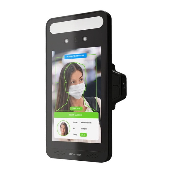
- Page 1 Temperature Measurement & Face Recognition Terminal Art. IPTHPAN02FA Please read this manual thoroughly before use and keep it for future reference...
- Page 2 Notes on Safet This product is intended to be supplied by a Listed Power Unit, marked with 'Limited Power Source', 'LPS' on unit, output rated minimum 12V/1 A, no more than 2000m altitude of operation and Tma=60 Deg.C. Do not attempt to disassemble the device;...
- Page 3 Disclaimer With regard to the product with internet access, the use of product shall be wholly at your own risks. Our company shall be irresponsible for abnormal operation, privacy leakage or other damages resulting from cyber-attack, hacker attack, virus inspection, or other internet security risks; however, our company will provide timely technical support if necessary.
- Page 4 2012/19/EU (WEEE directive): The Directive on waste electrical and electronic equipment (WEEE Directive). To improve the environmental management of WEEE, the improvement of collection, treatment and recycling of electronics at the end of their life is essential. Therefore, the product marked with this symbol must be disposed of in a responsible manner.
-
Page 5: Table Of Contents
Table of Contents Introduction ......................1 Network Connection ..................... 2 2.1 LAN ……………………………………………………………………………..2 2.1.1 Access through IP-Tool ................2 2.1.2 Directly Access through IE ................4 2.2 WAN ………………………………………………………………………....5 Temperature Measurement & Face Recognition Configuration ......9 3.1 Temperature Measurement Settings .............. - Page 6 6.3.5 Cable Disconnection .................. 33 6.3.6 Alarm In ……………………………………………………………… ....33 6.3.7 Alarm Out………..................34 6.4 Network Configuration ..................35 6.4.1 TCP/IP…………… ..................35 6.4.2 Port ………… ..................... 37 6.4.3 Server Configuration .................. 37 6.4.4 DDNS…………..................37 6.4.5 RTSP..…… ....................39 6.4.6 UPnP………...
-
Page 7: Introduction
Introduction This series of product is specially designed and developed for face recognition and temperature measurement applications, featuring non-contract temperature measurement, high performance and reliability, faster recognition and higher accuracy rate. Based on deep-learning algorithm, it combines temperature measurement, identity authorization and access control. It can be widely used in the entrances and exits of community, schools, hospitals, scenic areas, hotels, shopping malls, office buildings, public services and construction sites for body temperature measurement, identity authorization and access control. -
Page 8: Network Connection
Network Connection Connect IP-Cam via LAN or WAN. The details are as follows: 1.1 LAN In LAN, there are two ways to access: 1. access through IP-Tool; 2. directly access through Internet Explorer browser. 1.1.1 Access through IP-Tool Network connection: ①... - Page 9 For example, the IP address of your computer is 192.168.1.4. So the IP address of the camera shall be changed to 192.168.1.X. After modification, please enter the password of the administrator and click the “Modify” button to modify the setting. The default Password of the administrator is admin.
-
Page 10: Directly Access Through Ie
The system will pop up the above-mentioned textbox to ask you to change the default password. It is strongly recommended to change the default password for account security. If “Do not show again” is checked, the textbox will not appear next time. 1.1.2 Directly Access through Internet Explorer The default network settings are as shown below: IP address: 192.168.1.150... -
Page 11: Wan
Select “Properties” and then select internet protocol according to the actual situation (for example: IPv4). Next, click the “Properties” button to set the network of the PC. ② Open the IE browser and enter the default address of IP-CAM and confirm. ③... - Page 12 ① Make sure the camera is connected to the local network and then log in the Port Setup ② IP Setup ③ Go to the router’s management interface through IE browser to forward the IP address and port of the camera in the “Virtual Server”.
- Page 13 Router Setup ④ Open the IE browser and enter its WAN IP and http port to access. (for example, if the http port is changed to 81, please enter “192.198.1.150:81” in the address bar of web browser to access). Access through PPPoE dial-up Network connection Access the camera through PPPoE auto dial-up.
- Page 14 Access through static IP Network connection The setup steps are as follow: ① ② following IP address” and then enter the static IP address and other parameters. ③ Open the IE browser and enter its WAN IP and http port to access.
-
Page 15: Temperature Measurement & Face Recognition Configuration
Temp Measurement & Face Recognition Config 3.1 Temperature Measurement Settings After the network is connected, go to the web client. Click Measurement to go to the following interface. Enable Temperature Measurement, select Celsius or Fahrenheit temperature as needed and then set the high temperature threshold and the low temperature threshold. -
Page 16: Face Match Configuration
temperature alarm and save the images on an Micro-SD card. Trigger SD Recording: If selected, video will be recorded on an Micro-SD card on detecting abnormal temperature alarm. Trigger Email: If “Trigger Email” and “Attach Picture” are checked (email address must be set first in the Email configuration interface), the captured pictures and triggered event will be sent into those addresses. -
Page 17: Face Database Management
Deduplication Period: In the set period, delete the repeated comparison results. Similarity threshold: When the similarity of the captured face picture and the face picture added into the face database exceeds the similarity threshold, alarms will be triggered (check the box Alarm Out 1, Alarm Out 2). 3.3 Face Database Management Click “Face Database Management”... -
Page 18: Mask Detection
After adding face pictures, you can search them by name, gender, ID number and so on. Click “Modify” to change people information and click “Delete” to delete this face picture. 3.4 Mask Detection... - Page 19 Enable “Mask Detection” as needed. Set the alarm holding time. Set the alarm trigger options. Alarm Out: If enabled, alarm output will be triggered when the detected person doesn wear a mask. Trigger Audio Alarm: If enabled, the alarm voice will be heard when the detected person doesn’t wear a mask.
-
Page 20: Live View
Live View 4.1 Temperature Measurement & Face Recognition View 4.1.1 Temperature Measurement Requirements Some recommendations: The face image of the detected person shall be within the pre-defined face detection area. The detected face shall be 30cm~40cm away from the temperature measurement sensor. Please remove the hat/cap/helmet/hair covering the forehead. -
Page 21: Temperature Measurement & Face Recognition View
3. The installation height shall fit the height of the detected people. 4. Raise your wrist and then make your inside wrist point at the temperature measurement sensor (3~5cm away from the sensor). 4.1.2 Temperature Measurement & Face Recognition View After configuring temperature measurement and face match, the temperature and face match result can be viewed on the screen. -
Page 22: Live View Via Web
The system will measure the temperature and compare the captured face at the same time as shown below. When the captured face is not added to the face database or the similarity is lower than the pre-defined value, it will display “Match Failure” and the box will turn red. If the mask detection and “Trigger Audio Alarm”... - Page 23 The following table is the instructions of the icons on the live view interface. Icon Description Icon Description Original size Start/stop local recording Fit correct scale Zoom in Auto (fill the window) Zoom out Full screen Micro-SD card recording indicator Start/stop live view Sensor alarm indicator Start/stop two-way audio...
- Page 24 View the comparison details In area ②, click the compared face picture to bring up the following window. In this interface, you can view the detailed comparison information. Add captured face pictures to the face database Click a captured picture in area ①. This will bring a face picture adding box. Fill out the relevant information and click “Entry”...
-
Page 25: Access Control Settings
Access Control Settings 5.1 Door Lock Settings access control device is connected to the terminal, you can set unlocking mode in this interface. Unlocking Mode: three options--face recognition, normal temperature and mask. Please check as needed. By Face Recognition: if the capture face picture is successfully matched, the door can be unlocked. -
Page 26: Tampering Alarm Settings
Alarm Trigger Mode: Wiegand Input, Wiegand Output or Off can be selected. If the card reader is connected to the Wiegand interface, please select “Wiegand Input”. If the access controller is connected to the Wiegand interface, please select “Wiegand Output”. You can also select the alarm output as needed. -
Page 27: Other Configurations
Other Configurations In the Webcam client, choose “Config” to go to the configuration interface. Note: Wherever applicable, click the “Save” button to save the settings. 6.1 System Settings 6.1.1 Basic Information In the “Basic Information” interface, the system information of the device is listed. Some versions may support device ID and QR code. -
Page 28: Local Config
Select the time zone and DST as required. Click the “Date and Time” tab to set the time mode. 6.1.3 Local Config and recorded videos on the local PC. There is also an option to enable or disable the bitrate display in the recorded files. Additionally, the local smart snapshot (face snapshot) storage can be enabled/disable here. - Page 29 Micro-SD card Management Click the “Format” button to format the Micro-SD card. All data will be cleared by clicking this button. Click the “Eject” button to stop writing data to Micro-SD card. Then the Micro-SD card can be ejected safely. Snapshot Quota: Set the capacity proportion of captured pictures on the Micro-SD card.
- Page 30 Weekly schedule Set the alarm time from Monday to Sunday for a single week. Each day is divided in one hour increments. Green means scheduled. Blank means unscheduled. “Add”: Add the schedule for a special day. Drag the mouse to set the time on the timeline.
-
Page 31: Image Configuration
Set the format, resolution and quality of the image saved on the Micro-SD card and the snapshot interval and quantity and the timing snapshot here. Snapshot Quantity: The number you set here is the maximum quantity of snapshots. The actual quantity of snapshots may be less than this number. Supposing the occurrence time of an alarm event is less than the time of capturing pictures, the actual quantity of snapshots is less than the set quantity of snapshots. - Page 32 Brightness: Set the brightness level of the camera’s image. Contrast: Set the color difference between the brightest and darkest parts. Hue: Set the total color degree of the image. Saturation: Set the degree of saturation. Sharpness: Set sharpness level of the image edge. Noise Reduction: Decrease the noise and make the image more thorough.
-
Page 33: Video / Audio Configuration
Gain Mode: Choose “Auto” or “Manual”. If “Auto” is selected, the gain value will be automatically adjusted according to the actual situation. If “Manual” is selected, the gain value shall be set manually. The higher the value is, the brighter the image is. Schedule Settings of Image Parameters: Click the “Schedule”... -
Page 34: Osd Configuration
Three video streams can be adjustable. Resolution: The size of image. Frame rate: The higher the frame rate, the video is smoother. Bitrate type: CBR and VBR are optional. Bitrate is related to image quality. CBR means that no matter how much change is seen in the video scene, the compression bitrate will be kept constant. -
Page 35: Screen Brightness
Set time stamp, device name, OSD content and picture overlap here. After enabling the corresponding display and entering the content, drag them to change their position. Then click the “Save” button to save the settings. Picture Overlap Settings: Check “OSD Content1”, choose “Picture Overlay” and click “Browse” to select the overlap picture. -
Page 36: Face Exposure
White Light Mode: “OFF”, “Manual” or “Auto” is optional. In low illumination condition, this mode can be enabled. 6.2.6 Face Exposure To enable and set face exposure, please go to When the brightness of the captured face is not enough, it can be enabled. 6.3 Alarm Configuration 6.3.1 Exception This function can detect changes in the surveillance environment affected by the... - Page 37 1. Enable the applicable detection that’s desired. Scene Change Detection: Alarms will be triggered if the scene of the monitor video has changed. Video Blur Detection: Alarms will be triggered if the video becomes blurry. Enable Video Color Cast Detection: Alarms will be triggered if the video becomes obscured.
-
Page 38: Micro-Sd Card Full
the system responds to the blurriness of the image. The sensitivity value of Video Color Cast Detection: The higher the value is, the more sensitive the system responds to the obscuring of the image. 6.3.2 Micro-SD card Full Micro-SD card Full. 3. -
Page 39: Ip Address Conflict
4. Set alarm trigger options. Trigger alarm out, Email and FTP. The setup steps are the same as temperature measurement settings. Please refer to temperature measurement settings chapter for details. 6.3.4 IP Address Conflict Address Collision as shown below. 2. Click “Enable alarm” and set the alarm holding time. 3. -
Page 40: Alarm Out
1. Select the sensor ID, click “Enable” and set the alarm type, alarm holding time and sensor name. 2. Set alarm trigger options. The setup steps are the same as temperature measurement settings. Please refer to temperature measurement settings chapter for details. 3. -
Page 41: Network Configuration
Day/Night Switch Linkage: Having selected this mode, select the alarm type and then choose to open or close alarm out when the camera switches to day mode or night mode. Timing: Select the alarm type. Then click “Add” and drag the mouse on the timeline to set the schedule of alarm out;... - Page 42 Use IP address (take IPv4 for example)-There are two options for IP setup: obtain an IP address automatically by DHCP and use the following IP address. Please choose one of the options as needed. Test: Test the effectiveness of the IP address by clicking this button. Use PPPoE-Click the “PPPoE Config”...
-
Page 43: Port
6.4.2 Port RTSP port can be set. HTTP Port: The default HTTP port is 80. It can be changed to any port which is not occupied. HTTPS Port: The default HTTPs port is 443. It can be changed to any port which is not occupied. - Page 44 2. Apply for a domain name. 3. Enter the username, password, domain you apply for in the DDNS configuration interface 4. Click the “Save” button to save the settings.
-
Page 45: Rtsp
6.4.5 RTSP Select “Enable” to enable the RTSP function. Port: Access port of the streaming media. The default number is 554. RTSP Address: The RTSP address (unicast) format that can be used to play the stream in a media player. Multicast Address Main stream: The address format is “rtsp://IP address:rtsp... -
Page 46: Upnp
5. If the coding format of the video of the main stream is MJPEG, the video may be disordered at some resolutions. 6.4.6 UPnP If this function is enabled, the camera can be quickly accessed through UPnP name. 6.4.7 Email If you need to trigger Email when an alarm happens or IP address is changed, please set the Email here first. -
Page 47: Ftp
SMTP Port: The SMTP port. Send Interval(S): The time interval of sending email. For example, if it is set to 60 seconds and multiple motion detection alarms are triggered within 60 seconds, they will be considered as only one alarm event and only one email will be sent. If one motion alarm event is triggered and then another motion detection alarm event is triggered after 60 seconds, two emails will be sent. - Page 48 There is a certificate installed by default as shown above. Enable this function and save it. Then the camera can be accessed by entering https://IP: https port via the web browser (eg. https://192.168.1.150:443). A private certificate can be created if users don’t want to use the default one. Click “Delete”...
-
Page 49: Security Configuration
Click “Create” to create the certificate request. Then download the certificate request and submit it to the trusted certificate authority for signature. After receiving the signed certificate, import the certificate to the device. 6.5 Security Configuration 6.5.1 User Configuration Add user: 1. - Page 50 3. Enter user name in “User Name” textbox. 4. Enter the password in the “Password” and “Confirm Password” textbox. Please set the password according to the requirement of the password security level (Go to ce to set the security level). It is recommended to set a high level password that shall be composed of numbers, special characters, upper or lower case letters for your account security.
-
Page 51: Online User
2. Click the “Delete” button to delete the user. Note: The default administrator account cannot be deleted. 6.5.2 Online User An administrator user can kick out all the other users (including other administrators). 6.5.3 Block and Allow Lists The setup steps are as follows: Check the “Enable address filtering”... -
Page 52: Maintenance Configuration
Password Security Please set the password level and expiration time as needed. Password Level: Weak, Medium or Strong. Weak level: Numbers, special characters, upper or lower case letters can be used. You can choose one of them or any combination of them when setting the password. -
Page 53: Reboot
Import & Export Settings Configuration settings of the camera can be exported form a camera into another camera. 1. Click “Browse” to select the save path for import or export information on the PC. 2. Click the “Import Setting” or “Export Setting” button. Default Settings Click the “Load Default”... -
Page 54: Operation Log
1. Click the “Browse” button to select the save path of the upgrade file 2. Click the “Upgrade” button to start upgrading the firmware. 3. The device will restart automatically Caution! Do not close the browser or disconnect the camera from the network during the upgrade. -
Page 55: Search
Search 7.1 Image Search Click Search to go to the interface as shown below. Images that are saved on the Micro-SD card can be found here. Local Image Search Choose “Picture”—“Local”. Set time: Select date and choose the start and end time. Click to search the images. - Page 56 Click to return to the previous interface. Micro-SD card Image Search Choose “Picture”—“Micro-SD card”. Set time: Select date and choose the start and end time. Choose the alarm events at the bottom of the interface. Click to search the images. Double click a file name in the list to view the captured photos.
-
Page 57: Video Search
Icon Description Icon Description Close: Select an image and click Close all: Click this button to this button to close the image. close all images. Save all: Click this button to Save: Click this button to select select the path for saving the path for saving the image on all pictures on the PC. -
Page 58: Micro-Sd Card Video Search
Icon Description Icon Description Play button. After pausing the video, click this button Pause button to continue playing. Stop button Speed down Speed up Watermark display Enable / disable audio; drag the slider to adjust the volume after enabling audio. 7.2.2 Micro-SD card Video Search Click Search to go to the interface as shown below. - Page 59 Select the alarm events at the bottom of the interface. Select mix stream (video and audio stream) or video stream as needed. Double click on a file name in the list to start playback. The time table can be shown in 24H/12H/2H/1H format by clicking the corresponding buttons.
- Page 60 Click “Set up” to set the storage directory of the video files. Click “Open” to play the video. Click “Clear List” to clear the downloading list. Click “Close” to close the downloading window.
-
Page 61: Face Match Result Search
Face Match Result Search Click “Face Log” tab to go to the face recognition result search interface. Set the start time and end time and click “Search” to view the face recognition result. Red time tag means no comparison result. Green time tag means there is a comparison result. -
Page 62: Appendix Troubleshooting
C: Web port number has been changed: contact administrator to get the correct port number. D: Exclude the above reasons. Restore to default setting by Comelit Advance IP Tool. Comelit Advance IP tool cannot search devices. The anti-virus software in your computer may cause it. Please stop it and try to search device again. - Page 63 No sound can be heard. A:Audio input device is not connected. Please connect and try again. B: Audio function is not enabled at the corresponding channel. Please enable this function.
Need help?
Do you have a question about the IPTHPAN02FA and is the answer not in the manual?
Questions and answers