Table of Contents
Advertisement
Quick Links
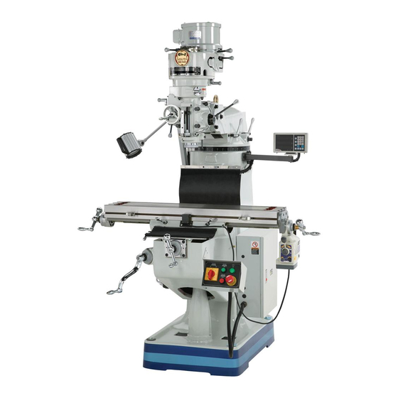
The Model SB1025F Milling Machine is the same machine as the Model SB1025 except for the
following:
•
Added a 3-Axis Fagor Digital Readout (DRO).
•
Longitudinal table travel reduced to 23
Except for the differences noted in this insert, all other content in the Model SB1025 Owner's Manual
applies to this machine. Before operating your new milling machine, you MUST read and understand
this insert, the entire Model SB1025 Owner's Manual, and the Fagor DRO Owner's Manual to reduce
the risk of injury when using this machine.
If you have any further questions about this manual insert or the differences between the Model
SB1025F and the Model SB1025, contact our Technical Support at (360) 734-1639 or email
sales@southbendlathe.com.
New & Changed Parts
REF
PART #
1008
PSB1026F1008
1008-1
PSB1026F1008-1
1008-2 PSB1026F1008-2
1008-3 PSB1026F1008-3
WARNING: No portion of this manual may be reproduced without written approval.
MODEL SB1025F
9" X 42" MILLING MACHINE w/DRO
PHONE: (360) 734-1540 •
1008-1
1008-3
1008-2
DESCRIPTION
DRO ASSEMBLY FAGOR 3-AXIS
DRO DISPLAY FAGOR 30iM
DRO X-AXIS SCALE FAGOR MKT-77
DRO Y-AXIS SCALE FAGOR MKT-37
Copyright © June, 2011 by South Bend Lathe Co.
#TS14204 Printed in USA
Manual Insert
www.southbendlathe.com
⁄
" due to DRO installation.
1
2
1008
1008-4
REF
PART #
1008-4 PSB1026F1008-4
1101
PSB1025F1101
1111
PSB1025F1111
1111
1101
DESCRIPTION
DRO Z-AXIS SCALE FAGOR MKT-47
MACHINE ID LABEL
MODEL NUMBER LABEL
Advertisement
Table of Contents

Subscribe to Our Youtube Channel
Related Manuals for South bend SB1025F


Summary of Contents for South bend SB1025F
- Page 1 MODEL SB1025F 9" X 42" MILLING MACHINE w/DRO Manual Insert www.southbendlathe.com PHONE: (360) 734-1540 • The Model SB1025F Milling Machine is the same machine as the Model SB1025 except for the following: • Added a 3-Axis Fagor Digital Readout (DRO). •...
- Page 2 M A N U A L I N S E R T Model SB1026F Mfg. Since 3/11 Model SB1025F Mill 9" x 42" with DRO, 3Phase Product Dimensions Weight................................1937 lbs. Width (side-to-side) x Depth (front-to-back) x Height..............63 x 58 x 81 in.
- Page 3 Approximate Assembly & Setup Time ......................1 Hour Serial Number Location ..................ID Label on Column Right Side Sound Rating ..............................55 dB ISO 9001 Factory ..............................No Certified by a Nationally Recognized Testing Laboratory (NRTL) ..............No Model SB1025F Page 2 of 3...
- Page 4 Halogen Work Light Allen-Bradley Electrical Controls Japanese NSK/NTN Bearings Table, Knee and Ram are Equipped with Dual Locking Mechanisms Turcite Coated Ways South Bend Brass Nameplate Meehanite Castings Typical South Bend "No Compromises" Fashion Model SB1025F Page 3 of 3...
- Page 5 9" X 42" MILLING MACHINE w/POWER FEED MODEL SB1024 - VARIABLE SPEED, 220V, SINGLE-PHASE MODEL SB1025 - 220V, 3-PHASE MODEL SB1026 - 220V, SINGLE-PHASE MODEL SB1025 MODEL SB1024 OWNER'S MANUAL Copyright © March, 2010. Revised March, 2015 (ST) For Machines Mfg. Since 8/09...
- Page 6 What did you like about it? Is there anything you would change to make it better? Did it meet your expectations for clarity, professionalism, and ease-of-use? South Bend Lathe, Inc. Technical Documentation Manager P.O. Box 2027 Bellingham, WA 98227 Email: manuals@southbendlathe.com...
-
Page 7: Table Of Contents
Table of Contents INTRODUCTION Initial Lubrication ..........25 About These Machines......... 3 Test Run ............. 25 ............. 3 Spindle Break-In ..........27 Foreword ............3 Inspections & Adjustments ....... 27 Capabilities .............. 3 Features OPERATION Front View Identification ........4 Operation Overview ........... - Page 8 SB1024 Head Machine Labels ......93 SB1024/SB1026 Electrical Components ..66 SB1024 Main Machine Labels ......94 SB1024/SB1026 Electrical Component SB1025/SB1026 Machine Labels ...... 95 Pictures ............... 67 WARRANTY & RETURNS .......... 97 South Bend Vertical Spindle Precision Milling Machine (circa 1958)
-
Page 9: Introduction
And finally, each machine is designed to accept today. As the owner of a South Bend milling a circulating coolant system with room for machine, you are now part of a great legacy. -
Page 10: Front View Identification
I N T R O D U C T I O N SB1024/SB1025/SB1026 For Machines Mfg. Since 8/09 Front View Identification Motor Belt Housing (see Pages 5–6) Spindle Brake Headstock (see Pages 5–6) Halogen Work Light Controls Left X-Axis Slotted Ball Handle Work Table Right X-Axis... -
Page 11: Model Sb1024 Belt Housing & Headstock Identification
I N T R O D U C T I O N For Machines Mfg. Since 8/09 SB1024/SB1025/SB1026 Model SB1024 Belt Housing & Headstock Identification Motor Assembly Low Range Variable Speed Indicator High Range Variable Speed Indicator Spindle Brake Variable Speed Handwheel Auto-Downfeed Rate Selector... -
Page 12: Model Sb1025/Sb1026 Belt Housing & Headstock Identification
I N T R O D U C T I O N SB1024/SB1025/SB1026 For Machines Mfg. Since 8/09 Model SB1025/SB1026 Belt Housing & Headstock Identification Motor Assembly Belt Tension Adjustment High/Low Lever Range Lever Motor Lock Spindle Brake Lever Spindle Speed Auto-Downfeed Range Selector Rate Selector... -
Page 13: Sb1024 Machine Specifications
I N T R O D U C T I O N For Machines Mfg. Since 8/09 SB1024/SB1025/SB1026 Model SB1024 Mill 9 x 42 1PH Var. Product Dimensions Weight................................2000 lbs. Width (side-to-side) x Depth (front-to-back) x Height..............63 x 58 x 87 in. Footprint (Length x Width)........................ - Page 14 I N T R O D U C T I O N SB1024/SB1025/SB1026 For Machines Mfg. Since 8/09 Main Specifications Operation Info Spindle Travel............................5 in. Max Distance Spindle to Column......................19 in. Max Distance Spindle to Table....................... 19 in. Longitudinal Table Travel (X-Axis)............
-
Page 15: Sb1025 Machine Specifications
I N T R O D U C T I O N For Machines Mfg. Since 8/09 SB1024/SB1025/SB1026 Model SB1025 Mill 9" x 42" 3PH Product Dimensions Weight................................1918 lbs. Width (side-to-side) x Depth (front-to-back) x Height..............63 x 58 x 81 in. Footprint (Length x Width)........................ - Page 16 I N T R O D U C T I O N SB1024/SB1025/SB1026 For Machines Mfg. Since 8/09 Main Specifications Operation Info Spindle Travel............................5 in. Max Distance Spindle to Column......................19 in. Max Distance Spindle to Table....................... 18 in. Longitudinal Table Travel (X-Axis)............
-
Page 17: Sb1026 Machine Specifications
I N T R O D U C T I O N For Machines Mfg. Since 8/09 SB1024/SB1025/SB1026 Model SB1026 Mill 9" x 42" 1PH Product Dimensions Weight................................1940 lbs. Width (side-to-side) x Depth (front-to-back) x Height..............63 x 58 x 86 in. Footprint (Length x Width)........................ - Page 18 I N T R O D U C T I O N SB1024/SB1025/SB1026 For Machines Mfg. Since 8/09 Main Specifications Operation Info Spindle Travel............................5 in. Max Distance Spindle to Column......................19 in. Max Distance Spindle to Table....................... 18 in. Longitudinal Table Travel (X-Axis)............
-
Page 19: Safety
S A F E T Y For Machines Mfg. Since 8/09 SB1024/SB1025/SB1026 Understanding Risks of Machinery Operating all machinery and machining equipment can be dangerous or relatively safe depending on how it is installed and maintained, and the operator's experience, common sense, risk awareness, working conditions, and use of personal protective equipment (safety glasses, respirators, etc.). - Page 20 S A F E T Y SB1024/SB1025/SB1026 For Machines Mfg. Since 8/09 Entanglement: Loose clothing, gloves, neckties, Chuck Keys or Adjusting Tools: Tools used to jewelry or long hair may get caught in adjust spindles, chucks, or any moving/ moving parts, causing entanglement, rotating parts will become dangerous amputation, crushing, or strangulation.
-
Page 21: Additional Milling Machine Safety
S A F E T Y For Machines Mfg. Since 8/09 SB1024/SB1025/SB1026 Additional Milling Machine Safety Understanding Controls: The mill is a Stopping Spindle: To reduce the risk of hand complex machine that presents severe injuries or entanglement hazards, DO NOT cutting or amputation hazards if used attempt to stop the spindle with your hand incorrectly. -
Page 22: Preparation
P R E P A R A T I O N SB1024/SB1025/SB1026 For Machines Mfg. Since 8/09 Preparation Overview Things You'll Need The purpose of the preparation section is to help During the setup process, operation, and you prepare your machine for operation. maintenance of the machine, you'll need the following items: The typical preparation process is as follows:... -
Page 23: Unpacking
P R E P A R A T I O N For Machines Mfg. Since 8/09 SB1024/SB1025/SB1026 Unpacking This item was carefully packaged to prevent damage during transport. If you discover any damage, please immediately call Customer Service at (360) 734-1540 for advice. You may need to file a freight claim, so save the containers and all packing materials for possible inspection by the carrier or its agent. -
Page 24: Cleaning & Protecting
P R E P A R A T I O N SB1024/SB1025/SB1026 For Machines Mfg. Since 8/09 Cleaning & Protecting Avoid chlorine-based solvents, such as The unpainted surfaces are coated at the factory acetone or brake parts cleaner that may with a heavy-duty rust preventative that damage painted surfaces. -
Page 25: Location
P R E P A R A T I O N For Machines Mfg. Since 8/09 SB1024/SB1025/SB1026 Location Weight Load Refer to the Machine Specifications for the Physical Environment weight of your machine. Make sure that the surface upon which the machine is placed will The physical environment where your machine bear the weight of the machine, additional is operated is important for safe operation and... -
Page 26: Lifting & Moving
P R E P A R A T I O N SB1024/SB1025/SB1026 For Machines Mfg. Since 8/09 Lifting & Moving Place the lifting web straps under the ram and connect them to the safety hook, as illustrated in Figure 6. Note: Place padding between the straps and the This machine and its mill to protect the ram and ways, and to... -
Page 27: Leveling & Mounting
P R E P A R A T I O N For Machines Mfg. Since 8/09 SB1024/SB1025/SB1026 Leveling & Mounting Bolting to Concrete Floors Generally, you can either bolt your machine to the floor or mount it on machine mounts. Although not required, we recommend that you secure the machine to the floor and level it while doing so. -
Page 28: Assembly
P R E P A R A T I O N SB1024/SB1025/SB1026 For Machines Mfg. Since 8/09 Assembly Secure the ball handles with the hex nuts removed in Step 1. Ball Handles Note: Tighten the hex nuts just until they are snug. -
Page 29: Way Covers
P R E P A R A T I O N For Machines Mfg. Since 8/09 SB1024/SB1025/SB1026 Way Covers Remove the four button-head cap screws shown in Figure 12 from the column and Remove the five button-head cap screws the rear of the table, position the rear shown in Figure 11 from the front of the way cover in place, then secure it with the saddle and knee, position the pleated way... -
Page 30: Power Connection
P R E P A R A T I O N SB1024/SB1025/SB1026 For Machines Mfg. Since 8/09 Power Connection SB1025 (220V 3-Phase) Full Load Amp Draw ......6/5.6 Amps Required Voltage Range ........ 220V Phase ............3-Phase Frequency ............60 Hz Electrocution or fire Minimum Circuit Size ...... -
Page 31: Initial Lubrication
P R E P A R A T I O N For Machines Mfg. Since 8/09 SB1024/SB1025/SB1026 Initial Lubrication Move the downfeed selector to the manual (forward) position so that the spindle does not downfeed during this test (refer to the The machine was fully lubricated at the Downfeed Operations section on Page 43 factory, but we strongly recommend that... - Page 32 P R E P A R A T I O N SB1024/SB1025/SB1026 For Machines Mfg. Since 8/09 Refer to the Table Movement section, Listen for abnormal noises and watch for beginning on Page 29, to understand how unexpected actions from the mill. The machine should run smoothly and without the power feed, table locks, and limit switch excessive vibration or rubbing noises.
-
Page 33: Spindle Break-In
P R E P A R A T I O N For Machines Mfg. Since 8/09 SB1024/SB1025/SB1026 Spindle Break-In Since the mill head was rotated parallel to the table for shipping purposes, you will need to tram the spindle with the table if your first Complete the spindle bearing break-in cut requires a 90°... -
Page 34: Operation
O P E R A T I O N SB1024/SB1025/SB1026 For Machines Mfg. Since 8/09 Operation Overview The purpose of this overview is to give an Loose hair, clothing, or example of a typical milling operation. Read jewelry could get caught through the steps below to better understand in machinery and cause the controls and functions described later in this... -
Page 35: Control Panel
O P E R A T I O N For Machines Mfg. Since 8/09 SB1024/SB1025/SB1026 Control Panel ON Button: Allows power flow to the motor. The spindle direction switch must be used to start the spindle rotation. Use Figures 15–16 and the following descriptions to understand the functions of the Power Lamp: Illuminates when the mill is mill control panel. -
Page 36: Graduated Index Rings
O P E R A T I O N SB1024/SB1025/SB1026 For Machines Mfg. Since 8/09 Graduated Index Rings The table ball handles and elevation crank have Always keep the table locked in place unless graduated index rings attached (see Figure table movement is required for your operation. -
Page 37: X-Axis Power Feed
O P E R A T I O N For Machines Mfg. Since 8/09 SB1024/SB1025/SB1026 X-Axis Power Feed H. X-Axis Ball Handle: Manually moves the table. The mill is equipped with a power feed unit for X-axis table movement. Refer to the illustration Graduated Index Ring: Display the distance in Figure 20 and the descriptions below of table travel in 0.001"... -
Page 38: Head Movement
O P E R A T I O N SB1024/SB1025/SB1026 For Machines Mfg. Since 8/09 Head Movement Always lock the head firmly in place after The head tilts 45° back and forth, and rotates 90° tilting or rotating it. Unexpected movement left and right, as shown in Figures 21–22. -
Page 39: Rotating Head
O P E R A T I O N For Machines Mfg. Since 8/09 SB1024/SB1025/SB1026 Rotating Head Tramming Spindle DISCONNECT MILL FROM POWER! After positioning the head at an angle and when your operation requires that the spindle axis be Loosen the four rotation lock bolts on the precisely perpendicular to the table, you must face of the head shown in Figure 24. - Page 40 O P E R A T I O N SB1024/SB1025/SB1026 For Machines Mfg. Since 8/09 Tools Needed Install the indicator holder into the spindle Dial Test Indicator or onto the quill, then mount the indicator (with at least 0.0005" resolution) ....1 onto it so that the point is as parallel to Indicator Holder the block as possible (see the illustration in...
- Page 41 O P E R A T I O N For Machines Mfg. Since 8/09 SB1024/SB1025/SB1026 Note: Generally, the goal in the next steps is to Place the parallel block directly under the get the difference of the indicator readings spindle and across the width of the table, as illustrated in Figure 28.
-
Page 42: Ram Movement
O P E R A T I O N SB1024/SB1025/SB1026 For Machines Mfg. Since 8/09 Ram Movement Always lock the head firmly in place after The ram travels back and forth 13" and rotates tilting or rotating it. Unexpected movement 360°... -
Page 43: Setting Spindle Speed
O P E R A T I O N For Machines Mfg. Since 8/09 SB1024/SB1025/SB1026 Setting Spindle Speed Setting Spindle Speed Range Setting the spindle speed range involves Using the correct spindle speed is important engaging and disengaging a spindle spline that for safe and satisfactory results, as well as uses gearing to increase or decrease the range of maximizing tool life. - Page 44 O P E R A T I O N SB1024/SB1025/SB1026 For Machines Mfg. Since 8/09 When the spindle speed range is changed, the direction of spindle rotation will reverse. ALWAYS know which way the spindle High is rotating before beginning the cutting operation.
- Page 45 O P E R A T I O N For Machines Mfg. Since 8/09 SB1024/SB1025/SB1026 Low Spindle Speed Range: Pull the knob of the spindle speed range selector (see Figure 33) out to disengage the detent pin, rotate Properly setting the spindle speed range for the selector clockwise to the front position, the Model SB1025/SB1026 involves correctly then release the knob.
- Page 46 O P E R A T I O N SB1024/SB1025/SB1026 For Machines Mfg. Since 8/09 Move the high/low range lever back to the When setting the mill to use the high spindle right side of the head (see Figure 33. speed range, the front spindle pulley must mesh with the spindle clutch.
-
Page 47: Setting Spindle Speed
O P E R A T I O N For Machines Mfg. Since 8/09 SB1024/SB1025/SB1026 Setting Spindle Speed Setting SB1024 Spindle Speed Start the spindle rotation. The Model SB1024 uses a variable pulley system to set infinite speeds within the speed range Slowly rotate the speed handwheel shown selected. - Page 48 O P E R A T I O N SB1024/SB1025/SB1026 For Machines Mfg. Since 8/09 Setting SB1025/SB1026 Spindle Speed Switch @ DISCONNECT MILL FROM POWER! SB1025 F1/R1 Low Spindle Remove the belt housing side covers on both Speed Range sides of the head to expose the V-belt and Motor pulleys, as shown in Figure 35.
-
Page 49: Downfeed Controls
O P E R A T I O N For Machines Mfg. Since 8/09 SB1024/SB1025/SB1026 Downfeed Controls SB1026 Spindle downfeed movement on the mill Low Spindle is controlled by three mechanisms: 1) The Speed Range coarse downfeed handle, 2) the fine downfeed Motor handwheel, and 3) the auto-downfeed system. - Page 50 O P E R A T I O N SB1024/SB1025/SB1026 For Machines Mfg. Since 8/09 Make sure the pin of the coarse downfeed handle hub is engaged with one of the Manual (Disengaged) Position detents on the downfeed sleeve (see Figure 40).
-
Page 51: Fine Downfeed Controls
O P E R A T I O N For Machines Mfg. Since 8/09 SB1024/SB1025/SB1026 Fine Downfeed Controls G. Downfeed Stop & Locking Wheel: Sets the depth of spindle downfeed. The stop There are a number of devices on the head that is threaded into position, then the locking are used with the fine downfeed handwheel or wheel is use to secure it in place. -
Page 52: Using The Auto-Downfeed System
O P E R A T I O N SB1024/SB1025/SB1026 For Machines Mfg. Since 8/09 Using the Auto-Downfeed System Position the auto-downfeed direction pin for the spindle travel that is correct for your When using the auto-downfeed system, the operation. It may be necessary to rock the spindle will move in the direction you choose fine downfeed handwheel back-and-forth to with the auto-downfeed direction pin. -
Page 53: Spindle Brake
O P E R A T I O N For Machines Mfg. Since 8/09 SB1024/SB1025/SB1026 Spindle Brake To avoid the risk of gear damage, always start spindle rotation before using the auto- downfeed rate selector. To avoid premature wear of the brake system, use the spindle brake ONLY after power to the spindle has been turned OFF. -
Page 54: Loading/Unloading Tooling
O P E R A T I O N SB1024/SB1025/SB1026 For Machines Mfg. Since 8/09 Loading/Unloading With one hand holding the tool in place, insert the drawbar into the spindle from the top of the head, then thread it into the tool Tooling (see Figure 47). -
Page 55: Maintenance
M A I N T E N A N C E For Machines Mfg. Since 8/09 SB1024/SB1025/SB1026 Maintenance Schedule Before Beginning Operations • Make sure the electric box door is closed and properly latched. • Turn the spindle direction switch to the off (middle) position to prevent spindle startup Always disconnect when connected to power (see Page 29). -
Page 56: Monthly Maintenance Chart
M A I N T E N A N C E SB1024/SB1025/SB1026 For Machines Mfg. Since 8/09 -50-... -
Page 57: Cleaning
M A I N T E N A N C E For Machines Mfg. Since 8/09 SB1024/SB1025/SB1026 Cleaning Lubrication Regular cleaning is one of the most important The mill has numerous moving metal-to- steps in taking good care of this lathe. Each metal contacts that require regular and proper operator is responsible for cleaning the machine lubrication to ensure efficient and long-lasting... -
Page 58: Quill
M A I N T E N A N C E SB1024/SB1025/SB1026 For Machines Mfg. Since 8/09 Table Ways (One-Shot Oiler) Oil Type ..Mobil Vactra 2 or ISO 68 Equivalent Failure to follow reasonable lubrication Oil Amount ....One Pull of Pump Handle practices as instructed in this manual for the Check/Add Frequency ..4–8 hrs. -
Page 59: Speed Range Bearing Sleeve (Sb1024 Only)
M A I N T E N A N C E For Machines Mfg. Since 8/09 SB1024/SB1025/SB1026 Speed Range Bearing Sleeve Headstock Gearing (SB1024 Only) Grease Type ......NLGI 2 or Equivalent Grease Amount ...Two Pumps of Grease Gun Oil Type ..Mobil Vactra 2 or ISO 68 Equivalent Check/Add Frequency ....40 hrs. -
Page 60: Ram Ways
M A I N T E N A N C E SB1024/SB1025/SB1026 For Machines Mfg. Since 8/09 Ram Ways Table Elevation Leadscrew Oil Type ..Mobil Vactra 2 or ISO 68 Equivalent Grease Type ......NLGI 2 or Equivalent Oil Amount ..........Thin Coat Grease Amount ........ - Page 61 M A I N T E N A N C E For Machines Mfg. Since 8/09 SB1024/SB1025/SB1026 Remove the hex nut and ball handle from the Brush a light coat of lubricant on the teeth power unit end of the longitudinal leadscrew of the bevel gear and the smaller drive gear (see Figure 57).
-
Page 62: Cleaning Coolant Reservoir
M A I N T E N A N C E SB1024/SB1025/SB1026 For Machines Mfg. Since 8/09 Cleaning Coolant Cleaning Tools Needed Reservoir Hex Wrench 3mm ..........1 Hex Wrench 10mm ..........1 Catch Pan .............. 1 To clean out the coolant reservoir: BIOLOGICAL &... -
Page 63: Machine Storage
M A I N T E N A N C E For Machines Mfg. Since 8/09 SB1024/SB1025/SB1026 Machine Storage • Loosen the belts to prevent them from stretching during storage. Post a reminder on the mill that the belts need to be re- To avoid rust problems or corrosion damage, installed or tensioned before resuming use the following information to protect your... -
Page 64: Service
S E R V I C E SB1024/SB1025/SB1026 For Machines Mfg. Since 8/09 Adjusting Gibs Gibs are tapered lengths of metal that are sandwiched between two moving surfaces. Gibs control the gap between these surfaces and how they slide past one another. Correctly adjusting the gibs is critical to producing good milling results. -
Page 65: Adjusting Leadscrew Backlash
S E R V I C E For Machines Mfg. Since 8/09 SB1024/SB1025/SB1026 Adjusting Leadscrew Longitudinal Leadscrew Backlash DISCONNECT MILL FROM POWER! Backlash Loosen the two cap screws on the leadscrew Leadscrew backlash is the amount of motion nut accessed from underneath the left side of the leadscrew rotates before the attached device the table, as shown in Figure 64. -
Page 66: Cross Leadscrew Backlash
S E R V I C E SB1024/SB1025/SB1026 For Machines Mfg. Since 8/09 Cross Leadscrew Backlash DISCONNECT MILL FROM POWER! Remove the hex nut and ball handle from the cross leadscrew. Note: In the next step, take care not to misplace the leadscrew key as you remove the parts. -
Page 67: Troubleshooting
TROU B LESHOOTI NG For Machines Mfg. Since 8/09 SB1024/SB1025/SB1026 If you need replacement parts, or if you are unsure how to do any of the solutions given here, feel free to call us at (360) 734-1540. Symptom Possible Cause Possible Solution Machine does not 1. - Page 68 TROU B LESHOOTI NG SB1024/SB1025/SB1026 For Machines Mfg. Since 8/09 Symptom Possible Cause Possible Solution Tool slips in collect. 1. Collet is not fully drawn into 1. Snug up the drawbar to fully seat the collet. spindle taper. 2. Wrong size collet. 2.
-
Page 69: Electrical
E L E C T R I C A L For Machines Mfg. Since 8/09 SB1024/SB1025/SB1026 Electrical Safety Instructions These pages are accurate at the time of printing. In the constant effort to improve, however, we may make changes to the electrical systems of future machines. Study this section carefully. If you see differences between your machine and what is shown in this section, call Technical Support at (360) 734-1540 for assistance BEFORE making any changes to the wiring on the machine. -
Page 70: Wiring Overview
E L E C T R I C A L SB1024/SB1025/SB1026 For Machines Mfg. Since 8/09 Wiring Overview Motor Junction Box SB1024/SB1026: See Page 66 and Figure 70 SB1025: See Page 69 and Figure 74 Work Lamp SB1024/SB1026: See Page 66 and Figure 69 SB1025: See Page 69 and... -
Page 71: Sb1024/Sb1026 Electrical Box
E L E C T R I C A L For Machines Mfg. Since 8/09 SB1024/SB1025/SB1026 SB1024/SB1026 Electrical Box SB1024/26 Electrical Box, See Figure 71 230V 380V 415V 460V TRANSFORMER Fuse Fuse Yung-Jeng A009-0383 110V RELAY CONTACTOR CONTACTOR CONTACTOR OMRON Allen Bradley Allen Bradley Allen Bradley... -
Page 72: Sb1024/Sb1026 Electrical Components
E L E C T R I C A L SB1024/SB1025/SB1026 For Machines Mfg. Since 8/09 SB1024/SB1026 Electrical Components Work Lamp Motor See Figure 69 See Figure 70 Ground Ground 6-20 Plug (As Recommended) Control Panel (Viewed From Behind) See Figure 71 Power Indicator Spindle... -
Page 73: Sb1024/Sb1026 Electrical Component Pictures
E L E C T R I C A L For Machines Mfg. Since 8/09 SB1024/SB1025/SB1026 SB1024/SB1026 Electrical Component Pictures Figure 70. Motor junction box. Figure 68. Electrical box. Figure 71. Control panel. Figure 69. Work lamp. -67-... -
Page 74: Sb1025 Electrical Box
E L E C T R I C A L SB1024/SB1025/SB1026 For Machines Mfg. Since 8/09 SB1025 Electrical Box Electrical Box, See Figure 72 230V 380V 415V 460V TRANSFORMER Fuse Fuse Fuse Yung-Jeng A009-0383 110V T1 T1 CONTACTOR CONTACTOR Allen Bradley Allen Bradley C09 400 C09 400... -
Page 75: Sb1025 Electrical Components
E L E C T R I C A L For Machines Mfg. Since 8/09 SB1024/SB1025/SB1026 SB1025 Electrical Components Work Lamp Motor See Figure 73 See Figure 74 Ground Ground 220 VAC L15-20 PLUG (as recommended) Control Panel (Viewed From Behind) See Figure 75 Power Spindle Direction/Speed Switch... -
Page 76: Sb1025 Electrical Component Pictures
E L E C T R I C A L SB1024/SB1025/SB1026 For Machines Mfg. Since 8/09 SB1025 Electrical Component Pictures Figure 74. SB1025 Motor junction box. Figure 72. SB1025 Electrical box. Figure 75. SB1025 Control panel. Figure 73. SB1025 Work lamp. -70-... -
Page 77: Parts
P A R T S For Machines Mfg. Since 8/09 SB1024/SB1025/SB1026 Headstock -71-... - Page 78 P A R T S SB1024/SB1025/SB1026 For Machines Mfg. Since 8/09 Headstock Parts List PART # DESCRIPTION PART # DESCRIPTION PSB10240449 ROUND KNOB 3/8-16 PSB10240037A CLUSTER GEAR SHAFT 18T/12T PSB10240002 PINION SHAFT LEVER PSB10240037A FEED DRIVE CLUSTER GEAR 23T PSB10240003 PINION SHAFT HUB PSB10240037A NEEDLE BEARING BZ66Z TIMKEN PSTB004...
- Page 79 P A R T S For Machines Mfg. Since 8/09 SB1024/SB1025/SB1026 Headstock Parts List PART # DESCRIPTION PART # DESCRIPTION PSB10240097 KNURLED KNOB SCREW M6-1 X 15 PCAP02M CAP SCREW M6-1 X 20 PSB10240098 SCRIBING LEVER PSB10240117 STOP SHAFT TRIP LEVER PSB10240099 REVERSE TRIP BALL LEVER SCREW PSB10240118...
-
Page 80: Quill
P A R T S SB1024/SB1025/SB1026 For Machines Mfg. Since 8/09 Quill Quill Housing 206A PART # DESCRIPTION PART # DESCRIPTION PSB10240201 SPINDLE R8 PSB10240210 SPANNER LOCK WASHER PSS03M SET SCREW M6-1 X 8 PSB10240211 SPANNER NUT PSB10240203 QUILL END CAP PSB10240212 QUILL SKIRT PSB10240204... -
Page 81: Sb1024 Gearbox
P A R T S For Machines Mfg. Since 8/09 SB1024/SB1025/SB1026 SB1024 Gearbox 307A 303A For Reference Only -75-... - Page 82 P A R T S SB1024/SB1025/SB1026 For Machines Mfg. Since 8/09 SB1024 Gearbox Parts List PART # DESCRIPTION PART # DESCRIPTION PSB10240301 GEARBOX PLATE PSB10240325 BELT PULLEY GEAR PK70M KEY 8 X 8 X 12 PCAP24M CAP SCREW M5-.8 X 16 303A PSB10240303A SPINDLE GEAR HUB ASSEMBLY PSB10240327 BULL GEAR PINION BEARING CAP...
-
Page 83: Sb1025/Sb1026 Gearbox
P A R T S For Machines Mfg. Since 8/09 SB1024/SB1025/SB1026 SB1025/SB1026 Gearbox For Reference Only For Reference Only -77-... - Page 84 P A R T S SB1024/SB1025/SB1026 For Machines Mfg. Since 8/09 SB1025/SB1026 Gearbox Parts List PART # DESCRIPTION PART # DESCRIPTION PN04 HEX NUT 5/8-11 PSS02M SET SCREW M6-1 X 6 PFH07M FLAT HD SCR M5-.8 X 10 PSB10240018 ROUND KNOB 1/4-20 PSB10250303 PULLEY FLANGE PSB10250320...
-
Page 85: Sb1024 Belt Housing
P A R T S For Machines Mfg. Since 8/09 SB1024/SB1025/SB1026 SB1024 Belt Housing 403A 403-1 403-2 403-3 403-4 403-5 For Reference Only -79-... - Page 86 PSS05M SET SCREW M5-.8 X 10 PSB10240466 TIMING PULLEY CLUTCH SLEEVE PCAP02M CAP SCREW M6-1 X 20 SB1319 SOUTH BEND NAMEPLATE 90MM PSB10240416 TOP BEARING COVER PS05M PHLP HD SCR M5-.8 X 8 P6007VV-N DEEP GROOVE BALL BEARING 6007VV NSK...
-
Page 87: Sb1025/Sb1026 Belt Housing
P A R T S For Machines Mfg. Since 8/09 SB1024/SB1025/SB1026 SB1025/SB1026 Belt Housing -81-... - Page 88 401-2 PSB10250401-2 MOTOR FAN (SB1025) PSB10250424 BRAKE HANDLE PIVOT RING 401-2 PSB10260401-2 MOTOR FAN (SB1026) SB1319 SOUTH BEND NAMEPLATE 90MM 401-3 PSB10250401-3 MOTOR JUNCTION BOX (SB1025) PS05M PHLP HD SCR M5-.8 X 8 401-3 PSB10260401-3 MOTOR JUNCTION BOX (SB1026) PRIV001M...
-
Page 89: Ram
P A R T S For Machines Mfg. Since 8/09 SB1024/SB1025/SB1026 -83-... - Page 90 P A R T S SB1024/SB1025/SB1026 For Machines Mfg. Since 8/09 Ram Parts List PART # DESCRIPTION PART # DESCRIPTION PCAP31M CAP SCREW M8-1.25 X 25 PSB10240517 TILT PIVOT STUD PRP90M ROLL PIN 8 X 30 PSB10240518 TILT LOCK BOLT BUSHING PSB10240503 GEAR 33T PSB10240519...
-
Page 91: Column, Knee, & Saddle
P A R T S For Machines Mfg. Since 8/09 SB1024/SB1025/SB1026 Column, Knee, & Saddle -85-... - Page 92 P A R T S SB1024/SB1025/SB1026 For Machines Mfg. Since 8/09 Column, Knee, & Saddle Parts List PART # DESCRIPTION PART # DESCRIPTION PSB10240601 COLUMN PSB10240637 CRANK CLUTCH PRIV001M FLUTED RIVET 2 X 5MM STEEL PSB10240638 FRONT DIAL RETAINER PSB10240603 INDICATOR PLATE PSB10240639 VERTICAL DIAL INCH...
-
Page 93: Table
P A R T S For Machines Mfg. Since 8/09 SB1024/SB1025/SB1026 Table -87-... - Page 94 P A R T S SB1024/SB1025/SB1026 For Machines Mfg. Since 8/09 Table Parts List PART # DESCRIPTION PART # DESCRIPTION PN01 HEX NUT 1/2-20 723A PSB10240723A LONGITUDINAL BALL HANDLE ASSY PSB10240702 HANDLE PSB10240723A LONGITUDINAL BALL HANDLE PSB10240703 CROSS FEED BALL HANDLE PSS08M SET SCREW M4-.7 X 5 704A PSB10240704A DIAL HOLDER ASSEMBLY...
-
Page 95: One-Shot Oiler
P A R T S For Machines Mfg. Since 8/09 SB1024/SB1025/SB1026 One-Shot Oiler Oil distributor PART # DESCRIPTION PART # DESCRIPTION PSB10240801 ELBOW JOINT M4 X 1/8 PT PCAP01M CAP SCREW M6-1 X 16 PSB10240802 T-JOINT PSB10240806 FLEXIBLE STEEL TUBE 4 X 500MM PSB10240803 ONE SHOT OILER ASSEMBLY PCAP38M... -
Page 96: Sb1024/Sb1026 Electrical Box
P A R T S SB1024/SB1025/SB1026 For Machines Mfg. Since 8/09 SB1024/SB1026 Electrical Box & Control Panel Electrical Box Control Panel PART # DESCRIPTION PART # DESCRIPTION PSB10240901 TRANSFORMER 24-440V YJ A009-0383 PSB10240911 CONTROL PANEL PSB10240902 FUSE HOLDER 30A PSB10240912 POWER INDICATOR ASSEMBLY PSB10240903 FUSE 30A... -
Page 97: Sb1025 Electrical Box & Control Panel
P A R T S For Machines Mfg. Since 8/09 SB1024/SB1025/SB1026 SB1025 Electrical Box & Control Panel Electrical Box Control Panel PART # DESCRIPTION PART # DESCRIPTION PSB10240901 TRANSFORMER 24-440V YJ A009-0383 PSB10250909 TERMINAL BAR 17-POST PSB10240902 FUSE HOLDER 30A PSB10240910 POWER RECEPTACLE 100V PSB10240903... -
Page 98: Accessories
P A R T S SB1024/SB1025/SB1026 For Machines Mfg. Since 8/09 Accessories 1002 1003 1001 1004 1007 1005 1006 PART # DESCRIPTION PART # DESCRIPTION 1001 PWR1921C CLOSED END WRENCH 19/21MM 1005 PSDF2 FLAT SCREWDRIVER #2 1002 PWR1214 WRENCH 12/14MM 1006 PSDP2 PHILLIPS SCREWDRIVER #2 1003... -
Page 99: Sb1024 Head Machine Labels
The owner of this machine MUST maintain the original location and readability of these safety labels. If any label is removed or becomes unreadable, REPLACE that label before using the machine again. Contact South Bend Lathe Co. at (360) 734-1540 or www.southbendlathe.com to order new labels. -
Page 100: Sb1024 Main Machine Labels
DESCRIPTION PART # DESCRIPTION 1107 PSBLABEL08VL ENTANGLEMENT HAZARD LABEL 1117 PSB10241117 220V 1PH LABEL 1108 SB1319 SOUTH BEND NAMEPLATE 90MM 1118 PSB10241118 110V 1PH 5.5A LABEL 1109 PSB10241109 SPINDLE SPEED DISPLAY LABEL 1119 PSB10241119 PLUG RECEPTACLE FIRE HAZARD LABEL 1110... -
Page 101: Sb1025/Sb1026 Machine Labels
DOWNFEED WARNING LABEL 1121 PSB10241121 CONTROL PANEL LABEL 1107 PSBLABEL08VL ENTANGLEMENT HAZARD LABEL 1122 PSBLABEL02VL DISCONNECT POWER LABEL 1108 SB1319 SOUTH BEND NAMEPLATE 90MM 1123 PSB10241123 QUALIFIED PERSONNEL NOTICE LABEL 1111 PSB10251111 MODEL NUMBER LABEL (SB1025) 1124 PSBPAINT01 SB GRAY TOUCH-UP PAINT... -
Page 103: Warranty & Returns
W A R R A N T Y This quality product is warranted by South Bend Lathe Company to the original buyer for one year from the date of purchase. This warranty does not apply to consumable parts, or defects due to any kind of misuse, abuse, negligence, accidents, repairs, alterations or lack of maintenance. - Page 104 Printed In Taiwan #JBTS12116...
Need help?
Do you have a question about the SB1025F and is the answer not in the manual?
Questions and answers