Table of Contents
Advertisement
Quick Links
ECX-DIO8
EtherCAT Digital I/O-Module
Hardware Manual
to Product E.3010.02
ECX-DIO8
Page 1 of 35
Hardware Manual • Doc.-No.: E.3010.21 / Rev. 1.1
esd electronic system design gmbh
Vahrenwalder Str. 207 • 30165 Hannover • Germany
http://www.esd.eu
Phone: +49 (0) 511 3 72 98-0 • Fax: +49 (0) 511 3 72 98-68
Advertisement
Table of Contents

Subscribe to Our Youtube Channel
Related Manuals for ESD ECX-DIO8


Summary of Contents for ESD ECX-DIO8
- Page 1 ECX-DIO8 Page 1 of 35 Hardware Manual • Doc.-No.: E.3010.21 / Rev. 1.1 esd electronic system design gmbh Vahrenwalder Str. 207 • 30165 Hannover • Germany http://www.esd.eu Phone: +49 (0) 511 3 72 98-0 • Fax: +49 (0) 511 3 72 98-68...
- Page 2 The information in this document has been carefully checked and is believed to be entirely reliable. esd makes no warranty of any kind with regard to the material in this document, and assumes no responsibility for any errors that may appear in this document. In particular descriptions and technical data specified in this document may not be constituted to be guaranteed product features in any legal sense.
- Page 3 I:\Texte\Doku\MANUALS\ECX\ECX-DIO8\Englisch\ECX-DIO8_Hardware_en_11.wpd File: 2013-06-03 Date of print: since ECX-DIO8 Rev. 2.01 PCB version: Changes in the chapters The changes in the document listed below affect changes in the hardware and firmware as well as changes in the description of facts only.
- Page 4 The permitted operating position is specified as shown (Figure 8). Other operating positions are not allowed. Do not open the housing of the ECX-DIO8 In order to prevent overvoltage damage due to thunder storm, unplug the ECX-DIO8 from CAN and the analog I/Os beforehand.
-
Page 5: Table Of Contents
9. Order Information ..............35 ECX-DIO8 Page 5 of 35 Hardware Manual •... - Page 6 This page is intentionally left blank. Page 6 of 35 ECX-DIO8 Hardware Manual • Doc.-No.: E.3010.21 / Rev. 1.1...
-
Page 7: Overview
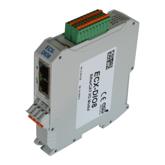
The ECX-DIO8 is an EtherCAT digital I/O-module. It is equipped with 8 digital I/Os, each available as input and output. The nominal I/O-voltage value is 24 V. Nominal output current is 0.5 A at 24 V. The ECX-DIO8 module provides industrial digital in-/outputs with two-wire connection in combination with service-friendly wiring of supply voltage. -
Page 8: Technical Data
Plastic housing for carrier rail mounting NS35/7,5 DIN EN 60715 width: 22.5 mm, length: 99 mm, constructional height: 114.5 mm Dimensions (dimensions without mating connectors) Weight 135 g Table 1: General technical data Page 8 of 35 ECX-DIO8 Hardware Manual • Doc.-No.: E.3010.21 / Rev. 1.1... -
Page 9: Ethercat® Slave Controller (Esc)
EtherCAT Slave ESC interface 2x RJ45, 100BASE-TX according to IEEE 802.3 Table 3: EtherCAT Slave Controller 2.4 Software Support Configuration is done by EtherCAT® master (XML file). ECX-DIO8 Page 9 of 35 Hardware Manual • Doc.-No.: E.3010.21 / Rev. 1.1... -
Page 10: Hardware Installation
Hardware-Installation 3. Hardware Installation 3.1 Connecting Diagram Fig. 2: Connections of the ECX-DIO8 module Attention: The pins 1,2 and 3 of the mounting rail bus connector are reserved and must not be connected! The connector pin assignment can be found on page 19 and following. -
Page 11: Leds
Fig. 3: Position of the LEDs in the front panel In the front panel the ECX-DIO8 module is equipped with 4 status LEDs (L, S, E, C) and 8 green LEDs (1- 8) for the digital I/O channels. The indicator states of the front panel LEDs are described in the following chapters. -
Page 12: Operation Of The Status Leds L, S, E, C
Colour Description Diagram state EEPROM error, EEPROM not loaded EEPROM LED200A Error EEPROM completely loaded ECX-DIO8 in INIT state, ETC is not initialised blinking ECX-DIO8 in PRE-OPERATIONAL state (fast) ETC Run green single flash ECX-DIO8 is in SAFE-OPERATIONAL state LED200B... -
Page 13: Status Of The Leds 1-8
6.0 V) and output status is ‘off’ input voltage level is higher than the upper switching threshold (input voltage 8.2 V) or output status is ‘on’ Table 6: Status of channels DIO1...DIO8 ECX-DIO8 Page 13 of 35 Hardware Manual • Doc.-No.: E.3010.21 / Rev. 1.1... -
Page 14: Ethercat Leds
Rx error occurred on the port Error yellow no physical layer Rx error on the port Table 7: Indicator states of the Status LEDs Page 14 of 35 ECX-DIO8 Hardware Manual • Doc.-No.: E.3010.21 / Rev. 1.1... -
Page 15: Installation Of The Module Using Inrailbus Connector
It is not a protection against accidental contact for persons. Note: The EG conformity (see page 34) can only be warranted, if the earthing via the mounting rail is made as described herein. ECX-DIO8 Page 15 of 35 Hardware Manual • Doc.-No.: E.3010.21 / Rev. 1.1... -
Page 16: Module Installation Using A Mounting Rail Bus Connector
ECX.. Place the ECX module with the DIN rail guideway on the top edge of the mounting rail. Figure 7 : Mounting ECX modules Page 16 of 35 ECX-DIO8 Hardware Manual • Doc.-No.: E.3010.21 / Rev. 1.1... - Page 17 Now the module is mounted on the mounting rail and connected to the InRailBus via the bus connector. Connect the bus connectors and the InRailBus if not already done. Figure 8: Mounted ECX-module ECX-DIO8 Page 17 of 35 Hardware Manual • Doc.-No.: E.3010.21 / Rev. 1.1...
-
Page 18: Connecting Power Supply To Inrailbus
Note: It is possible to remove individual devices from the ECX station without interrupting the InRailBus connection, because the contact chain will not be interrupted. Page 18 of 35 ECX-DIO8 Hardware Manual • Doc.-No.: E.3010.21 / Rev. 1.1... -
Page 19: Connector Assignment
(X101, pin 3/4 to X101, pin 1/2 ), the current may not exceed 8 A! Please refer also to the connecting diagram on page 10. Signal Description: P24... power supply voltage +24 V M24... reference potential ECX-DIO8 Page 19 of 35 Hardware Manual • Doc.-No.: E.3010.21 / Rev. 1.1... -
Page 20: Power Supply Voltage Via Inrailbus Connector (X100)
Do not connect! Do not connect! (PE_GND) Signal Description: P24... power supply voltage +24 V M24... reference potential FE... functional earth contact (EMC)(connected to mounting rail potential) Page 20 of 35 ECX-DIO8 Hardware Manual • Doc.-No.: E.3010.21 / Rev. 1.1... -
Page 21: Digital In/Outputs (X500)
1 and 11. These pins are connected to each other on the PCB. ECX-DIO8 Page 21 of 35 Hardware Manual • Doc.-No.: E.3010.21 / Rev. 1.1... -
Page 22: Ethercat Ports In, Out(X320A/B)
Permissible cable types: Cables of category 5e or higher have to be used to grant the function in networks with up to 100 Mbits/s. esd grants the EC conformity of the product if the wiring is carried out with shielded twisted pair cables of class SF/UTP or higher. -
Page 23: Conductor Connection/Conductor Cross Sections
2 conductors with same cross section, stranded, TWIN 1 mm² n.a. ferrules with plastic sleeve, max. Minimum AWG according to UL/CUL Maximum AWG according to UL/CUL n.a..not allowed ECX-DIO8 Page 23 of 35 Hardware Manual • Doc.-No.: E.3010.21 / Rev. 1.1... -
Page 24: Quick Start Guide
Read the safety notes at the beginning of the manual carefully before you start with the installation! Mount the ECX-DIO8 module Connect the interfaces (power supply voltage, EtherCAT, digital I/Os) End of hardware installation Continue with the software configuration... -
Page 25: Software
I/Os) as described on page10. Save the XML file of the ECX-DIO8 received from esd for example as: C : \ P r o g r a m m e \ E t h e r C A T C o n f i g u r a t o r \ E t h e r C A T \ E S D E C X - D I O 8 . x m l Start your EtherCAT Configurator. - Page 26 Scan Boxes... or Append Box... in the menu. If you choose Scan Boxes... continue with 8. If you choose Append Box..., the following dialog box Insert EtherCAT Device is opened. Page 26 of 35 ECX-DIO8 Hardware Manual • Doc.-No.: E.3010.21 / Rev. 1.1...
- Page 27 Software Select the esd ECX-DIO8 in this dialog window and confirm with OK. ECX-DIO8 Page 27 of 35 Hardware Manual • Doc.-No.: E.3010.21 / Rev. 1.1...
- Page 28 The ECX-DIO8 (Box 1) is now shown in the EtherCAT Configurator. The input and output variables contained in the XML file of the ECX-DIO8 are displayed as CANopen Process Data Objects(PDO). The PDOs are listed in the PDO List of the Process Data tab.
- Page 29 6070 , 01 1 Bit Input BOOL Channel Input IO Pin Channel 1 Channel 2 Channel 3 Channel 4 Channel 5 Channel 6 Channel 7 Channel 8 ECX-DIO8 Page 29 of 35 Hardware Manual • Doc.-No.: E.3010.21 / Rev. 1.1...
- Page 30 7070 , 01 1 Bit Output BOOL Channel Output IO Pin Channel 1 Channel 2 Channel 3 Channel 4 Channel 5 Channel 6 Channel 7 Channel 8 Page 30 of 35 ECX-DIO8 Hardware Manual • Doc.-No.: E.3010.21 / Rev. 1.1...
- Page 31 1 Bit Dummy6 BOOL OutputsLoopback of type byte, contains Digital Output Channel 1 Channel 2 Channel 3 Channel 4 Channel 5 Channel 6 Channel 7 Channel 8 ECX-DIO8 Page 31 of 35 Hardware Manual • Doc.-No.: E.3010.21 / Rev. 1.1...
- Page 32 ‘0' or ‘1' Value Meaning Error of digital output Dummy1-6 Do not use! These dummies are only implemented to work around a bug in the Beckhoff Configurator. Page 32 of 35 ECX-DIO8 Hardware Manual • Doc.-No.: E.3010.21 / Rev. 1.1...
-
Page 33: References
[2] Phoenix Contact GmbH & Co. KG, Blomberg., Technical data is taken from COMBICON Online Catalog, http://www.phoenixcontact.com/assets/interactive_ed/local_us/modules/0000160/index.html Printed-circuit board connector - FMC 1,5/ 5-ST-3,5 - 1952296, downloaded 2012-11-21 ECX-DIO8 Page 33 of 35 Hardware Manual • Doc.-No.: E.3010.21 / Rev. 1.1... -
Page 34: Declaration Of Conformity
8. Declaration of Conformity... -
Page 35: Order Information
Table 8: Order information PDF Manuals Manuals are available in English and usually in German as well. For availability of English manuals see the following table. Please download the manuals as PDF documents from our esd website www.esd.eu for free. Manuals Order No.
Need help?
Do you have a question about the ECX-DIO8 and is the answer not in the manual?
Questions and answers