Bose ACOUSTIMASS 10 Manual
Hide thumbs Also See for ACOUSTIMASS 10:

Advertisement

Part number change per supplement 188532-S3 11/2000
Specifications ................................................................................................................................... 2
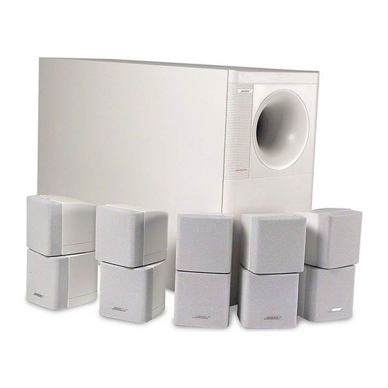
Figure 1. AM-10 Bass Module ......................................................................................................... 4
Disassembly/Assembly Procedures ........................................................................................... 5-6
Figure 2. Bass Module Exploded View ........................................................................................... 7
Figure 3. Cube Array Exploded View .............................................................................................. 7
Test Procedures ............................................................................................................................ 8-9
Part List Notes ................................................................................................................................ 10
AM-10 Bass Module Part List ........................................................................................................ 11
Figure 4. Bass Module Exploded View .......................................................................................... 11
Crossover Part List ........................................................................................................................ 12
Figure 5. Schematic Diagram REV 01 .......................................................................................... 12
Crossover Mechanical Part List .................................................................................................... 13
Figure 6. Crossover PCB Mechanical Layout ............................................................................... 13
Figure 7. Crossover PCB Etch Layout REV 01 ............................................................................. 13
Cube Array Part List ....................................................................................................................... 14
Figure 8. Cube Array Exploded View ............................................................................................. 14
AM-10 Packaging Part List ............................................................................................................ 15
Figure 9. Packaging Exploded View .............................................................................................. 15
This service manual has been updated with information from supplement 188532-S1.
This affects part numbers for the satellite speaker pivot o-ring, the satellite connectors and the
surround and center channel satellite Twiddlers. These changes resulted in changing the
service manual revision from Rev. 00 to Rev. 01.
This service manual has also been updated with information from supplement 188532-S2.
This affects part numbers for the woofers used in the bass module.
®
Contents
1

Advertisement

Table of Contents
loading

Summary of Contents for Bose ACOUSTIMASS 10

  • Page 1: Table Of Contents

    Part number change per supplement 188532-S3 11/2000 Contents Specifications ........................... 2 Acoustimass ® 10 Bass Module Description .................. 3 Figure 1. AM-10 Bass Module ......................4 Disassembly/Assembly Procedures ................... 5-6 Figure 2. Bass Module Exploded View ................... 7 Figure 3. Cube Array Exploded View ....................7 Test Procedures ..........................
  • Page 2: Specifications

    BOSE ® CORPORATION WHICH IS BEING FURNISHED ONLY FOR THE PURPOSE OF SERVICING THE IDENTIFIED BOSE PRODUCT BY AN AUTHORIZED BOSE SERVICE CENTER OR OWNER OF THE BOSE PRODUCT, AND SHALL NOT BE REPRODUCED OR USED FOR ANY OTHER PURPOSE.
  • Page 3: Acoustimass ® 10 Bass Module Description

    Left woofer Reproduces all left channel low frequency information. This woofer is loaded by the Acoustimass 10 enclosure in such a way as to produce deep bass energy. Right woofer Reproduces all right channel low frequency information. This woofer is loaded by the Acoustimass 10 enclosure in such a way as to produce deep bass energy.
  • Page 4 All front and surround channel bass energy is summed within this chamber in much the same way as a room would sum the bass energy from two separate bass modules. The key difference with internal bass summing is the results of summation are much better controlled because the summation conditions are already known (in a room with two bass sources, their distance from each other and their location within the room heavily influence bass summation and the loudspeaker designer cannot predict that ahead of...
  • Page 5: Disassembly/Assembly Procedures

    DISASSEMBLY/ASSEMBLY PROCEDURES 20 pins on the terminal cup line up with the BASS MODULE PCB. Press the PCB and the terminal cup together. Note: Numbers in parentheses correspond to the item call outs in Figure 2. 4.2 To prevent buzzes, make certain that the lamps are not touching one another.
  • Page 6 2.1 Line up the grille (13) so that the curved edges are located at the top and bottom. Push the grille onto the cube (2) until it snaps into place. The bottom grille should have the Bose ® logo in the lower right hand corner.
  • Page 7 SURROUND WOOFER (NOT SERVICEABLE) BAFFLE REMOVE WOOFER THROUGH OPENING Figure 2. Bass Module Exploded View (2X) (4X) BLACK (2X) GRAY BLACK GRAY (8X) Figure 3. Cube Array Exploded View...
  • Page 8: Test Procedures

    TEST PROCEDURES 1. Woofer Rub and Tick Test 4.2 Disconnect the left surround channel. If the sound output from the bass module 1.1 Apply a 10Vrms, 10Hz signal to the drops by 1/2, the woofer is in phase. If the front left and right input.
  • Page 9 TEST PROCEDURES 7. Crossover Test 7.1 Both woofer harnesses should be disconnected. Connect an 8.2Ω resistive load to the cube speaker output being tested. Apply a 1Vrms signal to the input at the frequency listed in the following table. Reference a dB meter to the applied signal. Measure the output listed in the following table.
  • Page 10: Part List Notes

    PART LIST NOTES 1. This part is not normally available from Customer Service. Approval from the Field Service Manager is required before ordering. 2. The individual parts located on the PCB are listed in the part list.
  • Page 11: Bass Module Part List

    AM-10 BASS MODULE PART LIST Item Description Part Number Notes Number Screw, Tapp, 6-13 x .375, pan 172783-06 Crossover Assy 187854-01 1, 2 Woofer, 5.25" 141393 Gasket, Woofer 104794-08 Terminal Cup 183641-1 Screw, Tapp, 8-11 x .75, Pan 172672-12 Grommet 117995 Bumper 187093...
  • Page 12: Crossover Part List

    CROSSOVER PART LIST Reference Description Part Number Designator PTC 11, 31 Polyswitch, 50V, 4mm 175233-1 PTC 21, 41, 51 Polyswitch, 60V, Disc, Rad 147185 DS11-13, 31-33 Lamp, 2.5A, 24VDC 117805 DS21, 41, 51 Lamp 141989 C21, 22, 41, 42, 51, 100uF, 50V, 20%, EL, BP, 142065 C11, 12, 31, 32...
  • Page 13: Crossover Mechanical Part List

    CROSSOVER MECHANICAL PART LIST Item D escription Part Q TY N um ber N um ber N ote C onn, Term inal, 1 PO S, Fem ale 147946 C onn, H eader, .15 137489-04 Tape, Foil, W /Liner 134636 W asher, Flat, .141", #5 108258-05 Screw , M ach, 4-40 x 1, Pan, Xrec 103146-16...
  • Page 14: Cube Array Part List

    CUBE ARRAY PART LIST Item Description Part Number Notes Number Encl., Lower, Black 141396-1 Encl., Lower, Arctic White 141396-2 Encl., Upper, Black 141397-1 Encl., Upper, Arctic White 141397-2 Pivot, Black 182604-1 Baffle, Red 173188-1 Baffle, Black 141398-1 Washer, Black 141402-1 Washer, Flat White 141402-2 O-Ring, Pivot...
  • Page 15: Packaging Part List

    AM-10 PACKAGING PART LIST Item Description Part Number QTY/ Number Assy Bumper, Recessed, Foot 142839 Carton, 2SC, AM10 184913-00 Bag, Poly, 13 x 33.5 x 11.5 x 3 mil 137847 Packing, Corner Post, Bass Mod 148044 Tray, Packing, Kraft 184914 Cable Assy, 20' x 5, RCA, BLK 183655-1 Cable Assy, 20' x 5, RCA, WHT...
  • Page 16 SPECIFICATIONS AND FEATURES SUBJECT TO CHANGE WITHOUT NOTICE ® BOSE CORPORATION THE MOUNTAIN FRAMINGHAM, MASSACHUSETTS USA 01701 P/N 188532 7/96: REV. 01 FOR TECHNICAL ASSISTANCE OR PART ORDERS, CALL 1-800-367-4008...
  • Page 17 ® ® ACOUSTIMASS -10 HOME THEATER SPEAKER SYSTEM Service Manual ©1996 Bose Corporation Part Number 188532...

This manual is also suitable for:

Am-10 sm

Table of Contents