
Summary of Contents for Promax BT-800K
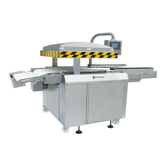
- Page 1 BT-800K elt Type Vacuum Packaging Machine Operation Manual Version 6.9.1 1915 E. Acacia Street, Ontario, CA91761, U.S.A : 1-909-923-3888 FAX : 1-909-923-3588 http://www.promarksvac.com S/N: QC SIGNATURE:...
-
Page 2: Table Of Contents
TABLE OF CONTENTS 1. SAFETY ........................1 1.1 SAFETY RECOMMENDATIONS ................1 1.2 PERSONAL SAFETY ....................2 1.3 FOOD SAFETY ......................3 2. INSTALLATION ..................... 4 2.1 UNPACKING ........................4 2.2 MOVING THE MACHINE ................... 4 2.3 MACHINE SPECIFICATIONS ..................5 2.4 ENVIRONMENT REQUIREMENTS ................ -
Page 3: Safety
Failure to follow these safety rules and take necessary precautions can result in serious injury or death as well as cause damage to the equipment. 1) Never operate or service your Promax / Promarks machine until you have read this manual completely and understand it fully. -
Page 4: Personal Safety
The following procedures and guidelines must be observed to avoid problems that can result in property damage, personal injury or death. If you have any questions regarding this information please contact Promax /Promarks, Inc. Service Department at (909) 481-3338. Hazardous Voltage: DANGER Electrical power must be disconnected and locked out before servicing or cleaning of the machine. -
Page 5: Food Safety
1.3 FOOD SAFETY While many Promax / Promarks machines are used in applications involving vacuum packaging and vacuum cooking, there are inherent risks associated with these techniques that can result in serious illness or death to the consumer of the food product. -
Page 6: Installation
TC Machines: Some of the smallest TC units may be lifted off of their wooden skid and moved manually. However Promax /Promarks recommends that moving even the smallest of their TC units should not be attempted by one person. The larger TC units should be lifted with the aid of a fork lift or other approved lifting aid. -
Page 7: Machine Specifications
2.3 BT-800K SPECIFICATION 2.4 ENVIRONMENT EQUIREMENTS The machine will be difficult to start if the air temperature is very low. This is caused by the increase in the vacuum pump’s oil viscosity due to the low temperature. To prevent this, please set... -
Page 8: Check Oil Level
2.5 CHECK OIL LEVEL Check the oil level only when the machine is not in operation and all vacuum built up in the chamber has been vented. Be aware that the oil may be very hot and avoid all contact. Checking the Oil Level * Check the oil level on a daily basis * When checking the oil level use the sight gauge shown in figure 1 below. -
Page 9: Operation Parameters
3.Operating Parameters PRESS SCREEN INTO MAIN MENU LEFT RIGHT DOWN MAIN MENU 1 1.AUTO/SEMI-AUTO ON AUTO 2.PUMPING MOTOR ON/OFF SWITCH 3.VACUUM ON/OFF SWITCH 4.START MACHINE OPERATING 5.STOP MACHINE STOP 6.SKIP NEXT ONE 7.DISPLAY PERCENTAGE&VACUUM DEGREE 8.VAC % TIME ,INTERMITTENT TIME 9.PURF MAIN MENU 2 1.EXIT... - Page 10 MANUAL CONTROL MENU 1 PRE-OPERATING NEED TO CHANGE MENU 2 MANUAL ON 1.VAC MOTOR ON/OFF 2.BELT MOTOR ON/OFF 3.OUT MOTOR ON /OFF MANUAL CONTROL MENU 2 PRE-OPERATING NEED TO CHANGE MENU 2 MANUAL ON 1.LID CLOSE ON/OFF 2.VACUUM ON/OFF 3.GAS ON/OFF 4.SEAL ON/OFF 5.HEAT ON/OFF 6.VACUUM RELEASE ON/OFF...
- Page 11 THREE SETS PASSWORD MANU 1.THIS MANU CAN MODIFY THREE SETS PASSWORD FOR THE OPERATOR 2.FACTORY SETTING : 1234,3456,5678. PARAMETER TIME CHANGE MENU MAIN MENU 2 INPUT ONE OF 3 SETS CORRECT PASSWORD THEN TO HERE TIME OPERATING MENU SETTING SETTING MENU VAC99%SET OIL CHG SET PRE-INSTALL 800 HOURS...
- Page 12 INPUT MENU CHECK X00-X07 CHECK X10-X17 OUTPUT MENU CHECK Y00-Y07 CHECK Y10-Y17 ULVUSUAL MENU PRESS DEL TO CLEAR UNUSUAL MESSAGE...
- Page 13 VACUUM DEGREE & PERCENTAGE OIL CHANGE TIME & READING-FINAL INPUT MENU 1 1. ACTION - ON 2. NO ACTION - OFF INPUT MENU 2 1. ACTION - ON 2.NO ACTION - OFF...
- Page 14 OUTPUT 1 1. ACTION - ON 2. NO ACTION - OFF OUTPUT MENU 2 1. ACTION - ON 2.NO ACTION - OFF INPUT-OUTPUT CONTROL MENU 1 1. MACHINE OPERATING CAN TO CONTROL CONDITION 2. ACTION LIGHT ON...
- Page 15 INPUT-OUTPUT CONTROL MENU 2 1.MACHINE OPERATING CAN TO CONTROL CONDITION 2.ACTION LIGHT ON ITEN SETTING MENU 1.CHANGE ITEM PRESS CLEAR NEW ITEN ENTER LIGHT 2.ITEN TIME SET 8 SETS ITEN 1 SETTING MENU 1. VACUUM CONTROL 2. VACUUM TIME 3. GAS TIME 4.
- Page 16 ITEM 2 SETTING MENU AS SAME AS MENU 1 ITEM 3 SETTING MENU AS SAME AS MENU 1 ITEM 4 SETTING MENU AS SAME AS MENU 1...
- Page 17 ITEM 5 SETTING MENU AS SAME AS MENU 1 ITEM 6 SETTING MENU AS SAME AS MENU 1 ITEM 7 SETTING MENU AS SAME AS MENU 1...
- Page 18 ITEM 8 SETTING MENU AS SAME AS MENU 1 ITEM SETTING KEY MANU 1. PRESS DISPLAY WINDOW (1234567) 2. ENTER ITEM NAME 3. PRESS ENTER TO COMPLETE 4. PRESS EXIT TO QUIT...
-
Page 19: Maintenance
4.MAINTENANCE 4.1 Basic Maintenance The following maintenance procedures should be followed no matter what model Promarks machine you own. 4.1.1 Daily Visual Inspection Your machine should have the following items inspected daily. If this inspection is performed daily prior to the start of your days production you will find that your machine will always perform consistently, last longer and suffer less down time. -
Page 20: Daily Cleaning
4.1.2 Daily cleaning Important Note: The following daily cleaning points are meant to help keep your machine in proper working order. They are in no way intended to provide the required level of sanitation needed for the packaging of food products. As noted earlier in this manual your company should consult with an expert in the sanitation field to design a robust sanitation routine when packaging food products. -
Page 21: Vacuum Valve Maintenance
b. Seal bars are located in the lid on larger SC Series machines and all DC Series machines. 2. Remove the screws that hold the Teflon holding strap in place. Refer to Figure A on the next page. 3. Remove the old Teflon cover. 4. -
Page 23: Maintenance Interval Chart
4.5 MAINTENANCE INTERVALS AND CHECK ITEMS Maintenance Intervals/ Daily Yearly Biyearly 3 ~ 5 years Note Bimonthly Quarterly Check items Keep the vacuum lid open after finished working and let vacuum pump running about 15 minutes. Check the oil level Check the sound of motor Oil come out from... -
Page 24: Troubleshooting
5. TROUBLESHOOTING 5.1 PROBLEMS AND CORRECTIONS Problem and Corrections - Review installation procedure section to ensure the installation is correct. If correct, the troubleshooting chart below lists possible problems, causes, corrections, and reference guide. Problem Cause Correction Control panel is under normal The KM1, QM1, MCB1, MCB2 Check each part and turn on the function, but vacuum pump does... -
Page 25: Pin D Type Terminal Wiring Connection Instructions
Problem Cause Correction No or improper sealing. Sealing wire is broken. Replace it. Sealing wire is loose. Tighten it. Insufficient pressure. Pressure bar is damaged, replace Replace it. Sealing transformer is damaged. Teflon tape or silicone rubber is Replace it. damaged. -
Page 26: Pneumatic Diagram
5.3 PNEUMATIC DIAGRAM... -
Page 27: Electrical Diagram
5.4 ELECTRICAL DIAGRAM Electrical diagram PNC-01 standard Motor FAZ- S2 POWER OUT-Packing-MOTOR Motor DC24V SUPPLE Sensor GP37W2 heater sealing 1000VA DOWN heater sealing 1000VA BELT-MOTOR Motor BRAKE FAZ- S2 220V FAZ- S2 (TOP COVER PREVENT COMPRESS DEVICE) 120VA Motor BT-800K(TB)220V... - Page 28 Electrical diagram BT-800K standard COM 0 P.L.C COM START COM 1 FLAT BELT M OTOR CLOCKW ISE(M 0) COM 2 INVERTER (1st SPEED SIGNAL)(M 3) STOP INVERTER (2nd SPEED SIGNAL)(M 4) COM 3 VACUUM PUM P M OTOR OUTFEED M OTOR CONTROL RELAY...
-
Page 29: Fabrication
6. FABRICATION 6.6 DRIVING BELT CONVEYOR 6.3 SEALING BAR, BOTTOM 6.4 CHAMBER LID 6.5 SEALING BAR, TOP 6.2 WORKING BED, BOTTOM 6.1 BODY 6.7 ELECTRICAL BOX... -
Page 30: Body Diagram
6.1 BODY Body Diagram B80K100000... - Page 31 6.1 BODY Body Diagram B80K100000...
- Page 32 6.1 BODY B80K100000...
- Page 33 B80K100P00 PART NO. DESCRIPTION QTY NOTES B80K101000 Frame B80K102000 Side door-L B80K103000 Side door-R B80K104000 Front Back door B80K105000 Front cover plate B80K106000 Back cover plate B80K107000 Lift cover plate B80K108000 Bearing fixed mount B80K109000 Bearing fixed mount 10 B80K100000 Sprocket fixed mount 11 B80K111000 Sprocket RS50x15T...
- Page 34 B80K100P01 PART NO. DESCRIPTION QTY NOTES 36 D80K235101 Nipple 1-1/2" 37 29090096 Tee branch 2" 38 29090072 Fitting,2"x1-1/2" 39 2728540 Bearing,pillow block UCFL208 40 27285353 Bearing,pillow block UCPH208 41 B80K901000 Pipe 42 27M82536 Base, leg 43 27121181 Casters 44 2883349 Door lock C408K 45 B80K802000 Panel...
- Page 35 B80K100P02 PART NO. DESCRIPTION QTY NOTES 71 2700408 Hex hd screw M8x20 72 27072032 Nut M8 73 2705301 Split lock washer M8 74 27280222 Bearing 6205ZZ 75 27060171 Ring S25 76 29119056 Regualtor,air main AW40-04BD 77 27010795 Socket set screw M14x40 78 2700464 Socket set screw M10x40 79 2708016...
- Page 36 B80K100P03 PART NO. DESCRIPTION QTY NOTES 106 2911216 Splenoid valve MVSC220-4E1-AC24 107 2CF-113 Bracket solenoid valve 108 2909328 Fitting JPL 602 109 29100050 Air regulator AR20-02H 110 2916001 Silencer 1/8" 111 2909002 Fitting 1/4"x1/4" 112 29093431 Fitting 1/4"x5/16" 113 2909333 Fitting JPC 802 114 29093603 Fitting SPC 10-02...
-
Page 37: Working Bed,Bottom
6.2 WORKING BED (BOTTOM) Working bed,Bottom Diagram B80K200000... - Page 38 B80K200P00 PART NO. DESCRIPTION QTY NOTES B80K201000 Welded body B80K202000 Welded body Front B80K225000 Belt adjust plate B80K227000 Roller B80K228000 Roller B80K231000 Adjust arm shaft B80K233000 Belt adjust arm BT80205000 Bearing holder BT80206000 Belt adjust slide block 10 BT80215000 Roller bearing mount 11 BT80218000 Motor fixed plate 12 BT80230002...
- Page 39 B80K200P01 PART NO. DESCRIPTION QTY NOTES 36 BT80221000 Washer 37 DC80211000 Nut-bottom sealing bar support shaft 38 2740168 O-ring 39 27004011 Hex hd screw M6x20 40 2705302 Split lock washer M6 41 2705151 Flat washer M6 42 2707204 Nut M6 43 2705189 Flat washer M10 44 B80K1350000 Roller fixed mount...
-
Page 40: Sealing Bar/ Cushion Bar Configurations
6.3.1 CUSHION BAR (FB) Cushion Bar Diagram B80K2FB000... - Page 41 B80K2FB000 PART NO. DESCRIPTION QTY NOTES B80K209001 Support mount(L) B80K210001 Support mount(R) BT80211000 Anti-rub washer B80K212001 Anti-rub guide BT80213000 Shaft bushing B80K214000 Flexible plate B80K215000 Shaft BT80236002 Filter plate B80K203000 Fixed plate 10 B80K223000 Cover 11 DC64221000 Support shaft - bottom sealing bar 12 B80K251000 Sealing bar(FB) 13 D80K226000...
-
Page 42: Cushion Bar (Fbpk)
6.3.2 CUSHION BAR (FBPK) Sealing Bar Bottom Diagram B80K2PK000... - Page 43 B80K2PK000 PART NO. DESCRIPTION QTY NOTES B80K209001 Support mount(L) B80K210001 Support mount(R) BT80211000 Anti-rub washer B80K212001 Anti-rub guide BT80213000 Shaft bushing B80K214000 Flexible plate B80K215000 Shaft BT80236002 Filter plate B80K203000 Fixed plate 10 B80K223000 Cover 11 BT80250001 Support shaft - bottom sealing bar 12 BT80251000 Cushlion bar(FBPK) 13 BT80255001...
- Page 44 B80K2PK001 PART NO. DESCRIPTION QTY NOTES 36 2704601 Set screw M6x6 BT80251A01 Cushion bar assembly(PK)
- Page 45 6.3.3 CUSHION BAR (FBTBPK) Sealing Bar Diagram B80K2TK000...
- Page 46 B80K2TB000 PART NO. DESCRIPTION QTY NOTES B80K209001 Support mount(L) B80K210001 Support mount(R) BT80211000 Anti-rub washer B80K212001 Anti-rub guide BT80213000 Shaft bushing B80K214000 Flexible plate B80K215000 Shaft BT80236002 Filter plate B80K203000 Fixed plate 10 B80K223000 Cover 11 BT80250001 Support shaft - bottom sealing bar 12 B80K246000 Sealing bar(FB) 13 3114471...
-
Page 47: Sealing Bar (Fbtbpk)
B80K2TB001 PART NO. DESCRIPTION QTY NOTES 36 2909459 Fitting SPL801 37 2704604 Set M5x10 38 D88K289000 Isolate plate 39 VA04277000 Spring 40 BT80255001 Support shaft 41 27030072 Round hd screw M4x35 42 B80K247000 Lid plate 43 DC12284000 Sealing wire plate 44 2704603 Set M6x10 45 D88K288000... -
Page 48: Chamber Lid,Top Diagram
6.4 CHAMBER LID DIAGRAM Chamber Lid, Top Diagram B80K400000... - Page 49 B80K400P00 PART NO. DESCRIPTION QTY NOTES B80K301000 Vacuum lid B80K335000 Bag retainer silicone B80K331000 Washer B80K332000 Washer B80K361000 Revetment B80K362000 Revetment 2861045 Straight connector PGA-16 2861060 Straight connector MGB-12L-05-G 2909043 Fitting A016 1/4"x3/8" 10 27001251 Hex hd screw M12x50 11 2705305 Split lock washer M12 12 2705137 Flat washer M12...
-
Page 50: Sealing Bar Configuations,Top
6.5.1 SEALING BAR, TOP (FB) Sealing Bar-Top Diagram B80K312A00... - Page 51 B80K312P00 PART NO. DESCRIPTION QTY NOTES B80K302000 Holder-sealing bar (F) B80K303000 Holder-sealing bar (B) BT80304A00 Pressure bag assembly B80K307000 Jointer-sealing bar B80K311001 Holder-sealing bar B80K312000 Sealing bar-top B80K313000 Fixed mount B80K314000 Electrode plate B80K315000 Copper connector-sealing 10 B80K316000 Connecting copper shaft 11 B80K317000 Spring fixed plate 12 B80K319000...
- Page 52 B80K312P01 PART NO. DESCRIPTION QTY NOTES 36 2704601 Socket set screw M6x6 37 B80K318000 Sealing element 38 2705105 Flat washer M5 39 2702254 Flat hd screw M6x20 40 B80K326000 Teflon type...
-
Page 53: Sealing Bar (Fb)
6.5.2 SEALING BAR, TOP (PK) Sealing Bar-Top Diagram BT80350A01... - Page 54 BT80350P00 PART NO. DESCRIPTION QTY NOTES B80K336000 Sealing bar plate(F) B80K33700 Sealing bar plate(B) B80K307000 Joint plate-plate BT80304A00 Pressure bag assembly BT80312001 Sealing bar-bottom BT80313000 Sealing element plate BT80318000 Sealing element BT80319000 Teflon tape BT80320000 Teflon tape 10 BT80356001 Sealing silicon 11 DC8035A000 Compression spring 12 BT8035B001...
- Page 55 BT80350P01 PART NO. DESCRIPTION QTY NOTES 36 2700414 Hex head screw M5x12 37 2705303 Split lock washer M5 38 2705105 Flat washer M4 39 2700423 Hex head screw M6x45 40 2700407 Hex head screw M8x80 41 2705301 Washer M8 42 2705304 Washer M10 43 D88K289000 Isolated plate...
-
Page 56: Belt Conveyor
6.5 BELT CONVEYOR Belt Conveyor B80K600000... - Page 57 B80K600P00 PART NO. DESCRIPTION QTY NOTES BT80601010 Conveyor frame B80K602000 Fixed plate(L) B80K603000 Fixed plate(R) BT80604000 Adjust plate BT80605000 Roller shaft BT80606000 Adjust roller BT80607000 Rubber roller BT80608000 Roller bearing mount BT80609000 Belt adjust plate 10 BT80610001 Belt adjust plate 11 BT80611000 Motor fixed plate 12 BT80612000...
- Page 58 B80K600P01 PART NO. DESCRIPTION QTY NOTES 36 2707204 Nut M6 37 27004011 Hex hd screw M6x20 38 BT80316000 Cover plate 39 2703304 Round head screw M4x6 40 BT80615000 Cover plate...
-
Page 59: Water Cooling
6.7 WATER COLLING Water Cooling & Pump mount Diagram B80K700000... - Page 60 B80K700P00 PART NO. DESCRIPTION QTY NOTES B80K401000 Tank B80K402000 Plate 29090082 Fitting 1/2" 2740449 Pump 29091361 Fitting 1/2"x3/4" 29093433 Fitting 1/2"x3/8" 29092183 Nipple 3/4"x3cm 29093266 Fitting 290932661 Fitting 10 2910609 Oil gun 11 29202351 Oil gauge 12 27072032 Nut M8 13 2705301 Split lock washer M8 14 2705151...
-
Page 61: Operator Box
6.8 OPERATOR BOX B80K800000... - Page 62 B80K800P00 PART NO. DESCRIPTION QTY NOTES B80K811000 Operator box B80K812000 Control panel lap B80K813001 Fixed bushing B80K814001 2883343 Handle 2827042 Carton sealer 2704604 Cap M5x10 2870489 AC24V Light 2870068 Emergency stop Switch 10 2890132 Buzzer...
-
Page 63: Electrical Boxes
6.9 ELECTRICAL BOX ITEM PART NO. DESCRIPTION SPECIFICATION Q’TY NOTE 2810739 TE CU11-B5 AC24 Contactor Option 2810746 TE LC1D32B7(AC24V) MOELLER 2810758 Contactor DILMP20(AC24V) 2811511 TE RHN-10K 0.67-1A 2811518 LR3D216 12-18A Overload Relay Option 2811531 TE RHU-10K (2.3-3.2A) 2810639 TE LR3D22(16-24A) 2830132 Relay RU4S-C-A24... - Page 64 Filter 2896571 Filter wave YC03T1L2 2801812 Switch FAZ-2-S2 2801822 Switch FAZ-S2 1P2A FAZ1~2 2801734 Breaker FAZ-C32/1 FAZ1~3 INV1 2805147 Inverter ANLY AMY-2 6S AC24V FFUBA FPT1-0010-A-A-D- 2913548 Switch SWITCH 2856034 Switch FFUBA BCT38L-M-2-C 28960020 0F-200-220V/0-24V.OF-24 Transformer Option 28960023 0F-400-440V/0-24.0F-24V TBSW-1I-120VA 28960022 OF-380-415/0-24 OF-24 Transformer...
Need help?
Do you have a question about the BT-800K and is the answer not in the manual?
Questions and answers