Advertisement
Available languages
Available languages
Quick Links
1.1
Installation options
Option: When fitting a gas hob above a drawer or standard housing unit, suitable precautions to
prevent contact. The panel underneath the hob must be easily removable to allow for any
servicing requirements with the casing of the hob which becomes very hot during operation.
The recommended method for overcoming this problem is to fix a wooden panel within the
cabinet at a distance of 0.59 in (15 mm) below the underside of the hob (see figure below). This
panel must have adequate ventilation to the rear.
Ventilation slot >1.18 in (30 mm)
1.2
Inserting and fixing the hob
Before inserting the hob into the work surface, place the adhesive seal (a) around the
underside edge of the hob. It is important to fix this gasket evenly, without gaps or
overlapping to prevent liquids from seeping underneath the hob.
-
Remove the pan stands and the burner caps, then turn the hob upside down, taking care
not to amage the ignition plugs and the thermocouples.
-
Place the gasket around the bottom edge of the hob as shown in the illustration overleaf
(left)
-
Place the hob in the installation opening and push it down so that the hob is resting
firmly on the cabinet.
-
Secure the hob in position using the fixing brackets supplied.
Fig. 4
Fig. 5
Advertisement

Related Manuals for Kitchen and Home 5Z-KHSSW

Summary of Contents for Kitchen and Home 5Z-KHSSW
- Page 1 Fig. 4 Fig. 5 Installation options Option: When fitting a gas hob above a drawer or standard housing unit, suitable precautions to prevent contact. The panel underneath the hob must be easily removable to allow for any servicing requirements with the casing of the hob which becomes very hot during operation. The recommended method for overcoming this problem is to fix a wooden panel within the cabinet at a distance of 0.59 in (15 mm) below the underside of the hob (see figure below).
- Page 2 Secure the hob to the underside of the workshop using the fixings provided. Screw one end of the bracket into the pre-drilled holes in the underside of the hob. The other end of the bracket should be located underneath the worktop to secure the hob in position. Gas connection ...
- Page 3 Replace the injectors with the corresponding injector from the table on page below (see Fig. 6). First, remove the burner caps and rings with a socket spanner “B”, unscrew injector “A” (see Fig. 6). The adjustment of the reduced rate position is as follows (Fig. 7): Light the burner and turn the knob to reduced rate position.
- Page 4 Injector replacement for LPG (G30/G31) Warning! Exchanging the nozzles must be operated by an expert of gas installation. Make sure to use the correct nozzles. You can find the correct nozzle diameter with the table below (2.11). The nozzle size is also printed on the nozzle itself. For the correct use in your country, check out the scope on the last pages of this manual.
- Page 5 special care to ensure that this is not out of the reach of children. There is a risk of suffocation! Disposal of waste equipment Equipment must be disposed of in accordance with the rules and regulations of the local waste disposal.
- Page 6 Abb. 4 Abb. 5 Einbau Bei der Montage eines Gasherdes über einer Schublade oder Standard-Gehäuseeinheit, müssen geeignete Vorkehrungen getroffen werden, um den Kontakt zu vermeiden. Die Platte unter dem Kochfeld muss leicht abnehmbar sein, falls Wartungsarbeiten am Gehäuse der Kochfläche nötig sind.
- Page 7 Sichern Sie das Kochfeld an der Unterseite der Arbeitsplatte mit den mitgelieferten Befestigungsteilen. Schrauben Sie ein Ende der Halterung in die vorgebohrten Löcher in der Unterseite des Kochfeldes. Das andere Ende der Halterung sollte sich unterhalb der Arbeitsplatte des Kochfeldes befinden.
- Page 8 Ersetzen Sie die Einspritzventile mit dem entsprechenden Injektor aus der folgenden Tabelle (siehe Abb. 6). Zuerst entfernen Sie die Brennerdeckel und Ringe und schrauben mit einem Steckschlüssel "B" die Einspritzdüse "A" (siehe Abb. 6) ab. Die Einstellung ist wie folgt (Abb. 7): Zünden Sie den Brenner und drehen Sie den Knopf. ...
- Page 9 Düsenaustausch für LPG (G30/G31) Warnung! Der Austausch der Düsen muss von einem Fachmann für Gasinstallation vorgenommen werden. Es muss sichergestellt werden, dass die richtigen Düsen verwendet werden. Die richtige Düsengröße entnehmen Sie der Tabelle aus 2.11. Die Größe der Düsen steht dazu auf der Düse. Beachten Sie außerdem die Ländereignung auf der letzten Seite dieser Anleitung.
- Page 10 Umweltschonende Entsorgung Entsorgung und Verpackung Die Verpackung Ihres Geräts besteht aus Materialien, die notwendig sind, um einen wirksamen Schutz beim Transport zu garantieren. Diese Materialien sind vollständig wiederverwertbar und verringern damit die Umweltbelastung. Entsorgen Sie die Verpackung in einer Tonne für recyclingfähige Materialien.
- Page 11 Demontage...
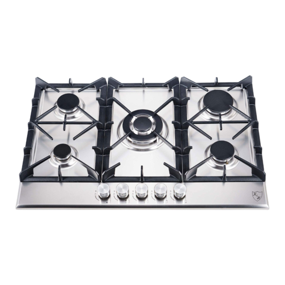
- Page 12 Model: 5Z-KHSSW Bezeichnung Description Unterschale Bottom plate assembly Feuerzeug Ignition box Stromkabel Power cord Anschlusskasten Wiring box Befestigungsplatte für Ventile Fixing plate for valves Gasventil Gas valve (1x 5pcs) Montage von Gasleitungen Gas pipes assembly Aluminiumbrennersockel für φ70 Aluminum burner base for φ70 burner (1x 2pcs) Brenner Injector for φ120 burner...
- Page 13 Ignition pin&wire for φ100 burner (120) Ignition pin&wire for φ70 burner (560) Ignition pin&wire for φ70 burner (470) 2# Zündstift Ignition pin&wire for φ50 burner (750) Fixing clamp for ignition pin (1x 4pcs) Wasserdichter Silikonring für Knopf Water proof silicone ring for knob (1x 5pcs) Knopf knob (1x 5pcs)
Need help?
Do you have a question about the 5Z-KHSSW and is the answer not in the manual?
Questions and answers