
Related Manuals for SMC Sierra Monitor FieldServer QuickServer PS-QS-1010


Summary of Contents for SMC Sierra Monitor FieldServer QuickServer PS-QS-1010
- Page 1 FieldServer QuickServer Start-up Guide PS-QS-1010/1011, PS-QS-1510/1511 APPLICABILITY & EFFECTIVITY Effective for all systems manufactured after March 2020. Document Revision: 2.H T18600...
- Page 2 QuickServer Start-Up Guide Technical Support ProSoft Technology, Inc. is a provider of FieldServer QuickServers. For Technical Support call +1 661.716.5100 Contact Information...
-
Page 3: Table Of Contents
QuickServer Start-Up Guide TABLE OF CONTENTS QuickServer Description ........................6 Supplied Equipment ..........................6 Certifications ............................7 BTL Mark – BACnet Testing Laboratory..................7 LonMark Certification ........................7 QuickServer Setup ..........................8 Mounting ............................8 Dimensions ............................. 9 4.2.1 Dimension Drawing FS-QS-1X10-XXXX ................. 9 4.2.2 Dimension Drawing FS-QS-1XX1-XXXX ................ - Page 4 QuickServer Start-Up Guide Appendix A.4.2. Configuring FieldServer as SSL/TLS Client .............. 34 Appendix A.4.2.1. Simple Secure Client Configuration ..............34 Appendix A.4.2.2. Limit Server Access ................... 34 Appendix A.4.2.3. Certificate Validation Options ................34 Appendix A.4.2.4. Set up Client Certificate ..................34 Appendix B Vendor Information –...
- Page 5 QuickServer Start-Up Guide LIST OF FIGURES Figure 1: DIN Rail ............................8 Figure 2: FS-QS-1X10-XXXX........................9 Figure 3: FS-QS-1XX1-XXXX ........................10 Figure 4: FS-QS-123X models with RS-422 ....................11 Figure 5: Bias Resistor Jumper ........................12 Figure 6: Termination Resistor Jumper ....................... 13 Figure 7: Power Jumper Switch ........................
-
Page 6: Quickserver Description
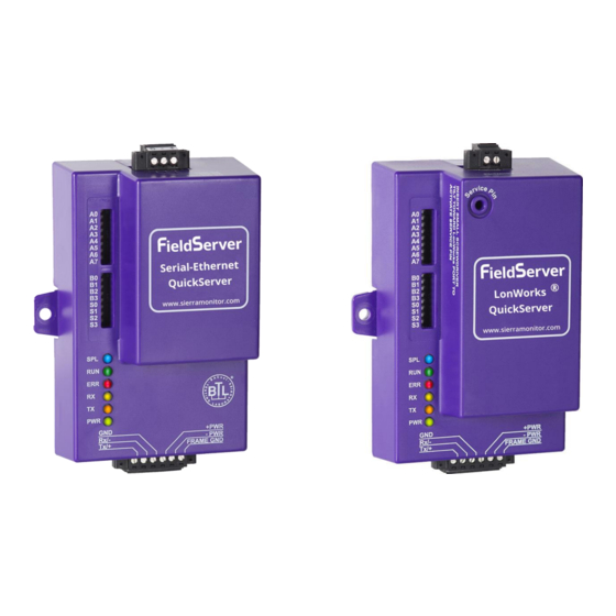
QuickServer Start-Up Guide QUICKSERVER DESCRIPTION QuickServer is a high performance, cost effective Building and Industrial Automation multi-protocol gateway providing protocol translation between serial, Ethernet, and LonWorks devices and networks. NOTE: For troubleshooting assistance refer to Appendix B, or any of the troubleshooting appendices in the related driver supplements. -
Page 7: Certifications
QuickServer Start-Up Guide CERTIFICATIONS BTL Mark – BACnet Testing Laboratory The BTL Mark is a symbol that indicates that a product has passed a series of rigorous tests conducted by an independent laboratory which verifies that the product correctly implements the BACnet features claimed in the listing. The mark is a symbol of a high-quality BACnet product. -
Page 8: Quickserver Setup
QuickServer Start-Up Guide QUICKSERVER SETUP Mounting The following mounting options are available: • Product comes with tabs for wall or surface mount. These can be snapped off if not required. • DIN rail mounting bracket – Included in the accessory kit or ordered separately (part # FS-8915-35-QS). -
Page 9: Dimensions
QuickServer Start-Up Guide Dimensions 4.2.1 Dimension Drawing FS-QS-1X10-XXXX R1 Port R2 Port Figure 2: FS-QS-1X10-XXXX Page 9 of 59... -
Page 10: 4.2.2 Dimension Drawing Fs-Qs-1Xx1-Xxxx
QuickServer Start-Up Guide 4.2.2 Dimension Drawing FS-QS-1XX1-XXXX LonWorks Port R2 Port Figure 3: FS-QS-1XX1-XXXX Page 10 of 59... -
Page 11: Dimension Drawing Fs-Qs-123X Models With Rs-422
QuickServer Start-Up Guide 4.2.3 Dimension Drawing FS-QS-123X Models with RS-422 R1 Port R2 Port Figure 4: FS-QS-123X models with RS-422 Page 11 of 59... -
Page 12: R2 Port Jumper Settings
QuickServer Start-Up Guide R2 Port Jumper Settings Gently remove the QuickServer enclosure to access the jumpers on the unit. 4.3.1 RS-485 Port NOTE: The following Sections only apply to QuickServer models: FS-QS-1011 and FS-QS-1211. 4.3.1.1 Bias Resistors Bias Resistor Jumper Figure 5: Bias Resistor Jumper The QuickServer bias resistors are used to keep the RS-485 bus to a known state, when there is no transmission on the line (bus is idling), to help prevent false bits of data from being detected. -
Page 13: 4.3.1.2 Termination Resistor
QuickServer Start-Up Guide 4.3.1.2 Termination Resistor Termination Resistor Jumper Figure 6: Termination Resistor Jumper Termination resistors are also used to reduce noise. These pull the two lines of an idle bus together. However, they would override the effect of any bias resistors, if connected. Page 13 of 59... -
Page 14: 4.3.1.3 Power Jumper Settings
QuickServer Start-Up Guide 4.3.1.3 Power Jumper Settings Power Jumper Switch in position “A” Figure 7: Power Jumper Switch The QuickServer Carrier Board power jumper is set to position A by default but can be changed to position B for other power supply requirements. Position A: The Carrier makes use of a full-wave rectifying bridge. -
Page 15: 4.3.2 M-Bus Port: Master/Slave Jumper
QuickServer Start-Up Guide 4.3.2 M-Bus Port: Master/Slave Jumper NOTE: The following only applies to models: FS-QS-1A50, FS-QS-1A51, FS-QS-1B51, FS-QS-1B51, FS-QS-1C51 and FS-QS-1C51. The Master/Slave jumper is used to set the M-Bus hardware as a Master or Slave device (indicated by the labels on the board). -
Page 16: R1 Port Small Dip Switches
QuickServer Start-Up Guide R1 Port Small DIP Switches Gently remove the QuickServer enclosure to access the small DIP switches for the R1 Port. 4.4.1 RS-485 Port NOTE: The following only applies to QuickServer models FS-QS-1XX0 or all non-LonWorks models. Bias Resistor Switch End of Line Switch Figure 9: Bias Resistor DIP Switches &... -
Page 17: Installing The Quickserver
QuickServer Start-Up Guide INSTALLING THE QUICKSERVER RS-485 5.1.1 RS-485 Connection R2 Port A- SG Figure 10: RS-485 R2 Connection Port Connect to the 3 pins on the left-hand-side of the 6-pin connector as shown. The following Baud Rates are supported on the R2 Port: 4800, 9600, 19200, 38400, 57600, 115200 For connection details to RS-232 or RS-422, refer to Appendix... -
Page 18: Quickserver Lonworks (Fs-Qs-1Xx1-Xxxx)
QuickServer Start-Up Guide QuickServer LonWorks (FS-QS-1XX1-XXXX) Connect the QuickServer to the LonWorks terminal using a twisted pair non-shielded cable. LonWorks Service Pin LonWorks Terminal Figure 12: LonWorks Commissioning and Port To commission the QuickServer LonWorks port, insert a small screwdriver in the commissioning hole on the face of the QuickServer’s enclosure to access the Service Pin. -
Page 19: Rs-232 Connection R2 Port (Only Available On Fs-Qs-122X Models)
QuickServer Start-Up Guide RS-232 Connection R2 Port (only available on FS-QS-122X Models) Figure 14: RS-232 R2 Connection Port Refer to Appendix A2 for further hardware connection options. The following Baud Rates are supported on the R2 Port: 4800, 9600, 19200, 38400, 57600, 115200 Page 19 of 59... -
Page 20: Operation
QuickServer Start-Up Guide OPERATION Power Up the Device Apply power to the device. Ensure that the power supply used complies with the specifications provided. Ensure that the cable is grounded using the “Frame GND” terminal. The QuickServer is factory set for 9-30V DC or 12-24V AC. -
Page 21: Connecting To The Quickserver
QuickServer Start-Up Guide Connecting to the QuickServer 6.3.1 Using the FieldServer Toolbox to Discover and Connect to the QuickServer • Install the Toolbox application from the USB drive or download it from the Sierra Monitor website. • Use the FS Toolbox application to find the QuickServer and launch the FS-GUI. NOTE: If the connect button is greyed out, the QuickServer’s IP Address must be set to be on the same network as the PC. -
Page 22: Set Ip Address Of The Quickserver Using Fs-Gui
QuickServer Start-Up Guide Set IP Address of the QuickServer Using FS-GUI • From the FS-GUI home page, click on setup and then Network Settings to enter the Edit IP Address Settings menu. • Modify the IP Address (N1 IP Address field) of the QuickServer Ethernet port. •... -
Page 23: Configuring The Quickserver
QuickServer Start-Up Guide CONFIGURING THE QUICKSERVER Retrieve the Sample Configuration File The configuration of the QuickServer is provided to the QuickServer’s operating system via a comma- delimited file called “CONFIG.CSV”. If a custom configuration was ordered, the QuickServer will be programmed with the relevant device registers in the Config.csv file for the initial start-up. -
Page 24: Load The Updated Configuration File
QuickServer Start-Up Guide Load the Updated Configuration File 7.3.1 Using the FS-GUI to Load a Configuration File • In the main menu of the FS-GUI screen, click “Setup”, then “File Transfer” and finally “Update”. • Browse and select the .csv file, open, then click “Submit”. Figure 20: FS-GUI Loading Files •... -
Page 25: 7.3.2 Retrieve The Configuation File For Modification Or Backup
QuickServer Start-Up Guide 7.3.2 Retrieve the Configuation File for Modification or Backup To get a copy of the configuration file for modifying or backing up a configuration on a local computer, do the following: • In the main menu of the FS-GUI screen, click “Setup”, then “File Transfer”. Figure 21: Retrieve Configuration File •... -
Page 26: Test And Commission The Quickserver
QuickServer Start-Up Guide Test and Commission the QuickServer • Connect the QuickServer to the third party device(s), and test the application. • From the landing page of the FS-GUI click on “View” in the navigation tree, then “Connections” to see the number of messages on each protocol. Figure 22: FS-GUI Connections Page Page 26 of 59... -
Page 27: Appendix A Useful Features
QuickServer Start-Up Guide Appendix A Useful Features Appendix A.1. RS-422 Connection R2 Port NOTE: The following only applies to models: FS-QS-1230 and FS-QS-1231. RS-422 is a full duplex multi-drop multi-master differential bus. It can be wired to conform to a RS-485 network when less wiring/cabling is used (due to being less expensive to install), but then it becomes a half-duplex multi-drop multi-master differential bus. -
Page 28: Appendix A.1.1. Connection And Operation Via The Rs-422 Port
QuickServer Start-Up Guide Appendix A.1.1. Connection and Operation via the RS-422 Port 5-pin RS-422 3-pin Power Connector Connector Figure 24: RS-422 Connectors RS-422 Connector Pin 1-2: TX +/- (Differential TX outputs: All + signals must be connected to each other, and same applies to - signals;... -
Page 29: Appendix A.2. Knx Connection R2 Port
QuickServer Start-Up Guide Appendix A.2. KNX Connection R2 Port NOTE: The following only applies to models: FS-QS-1240 and FS-QS-1241. The KNX QuickServer is used to transfer data to and from devices using KNX protocol. The KNX driver enables data access from KNX networks to other FieldServer protocols. Most KNX data-point types are supported, allowing communication to almost any kind of KNX device in an installation, such as temperature sensors, shutters, light switches, actuators, alarms, etc. -
Page 30: Appendix A.3. M-Bus Connection R2 Port
QuickServer Start-Up Guide Appendix A.3. M-Bus Connection R2 Port NOTE: The following only applies to models: FS-QS-1A50, FS-QS-1A51, FS-QS-1B50, FS-QS-1B51, FS-QS-1C50 and FS-QS-1C51. The M-Bus driver allows the FieldServer to transfer data to and from devices using M-Bus protocol. The Fieldbus connection is included with the FieldServer. -
Page 31: Appendix A.4. Ssl/Tls For Secure Connection
QuickServer Start-Up Guide Appendix A.4. SSL/TLS for Secure Connection SSL/TLS (Secure Sockets Layer/Transport Layer Security) is a security technology for establishing an encrypted connection between a server and a client. This allows the secure transfer of data across untrusted networks. These functions are supported on the following: FS-QS-1011 or FS-QS-1211 with a serial number starting with 15 or later (indicating the year it shipped). -
Page 32: Appendix A.4.1.2. Limiting Client Access
QuickServer Start-Up Guide Appendix A.4.1.2. Limiting Client Access In addition to TLS_Port parameter also add Validate_Client_Cert in the connections section of the configuration file and set it to “Yes”. Connections Adapter , Protocol , TLS_Port , Validate_Client_Cert , Modbus/TCP , 1502 , Yes The configuration above sets the FieldServer to request and verify a client’s certificate against its internal authority file before accepting connection. -
Page 33: Appendix A.4.1.4. Certificate Validation Options
QuickServer Start-Up Guide Appendix A.4.1.4. Certificate Validation Options If connections must be limited to only a particular domain (vendor devices), include Check_Remote_Host to specify the domain/host name. Connections Adapter , Protocol , TLS_Port , Validate_Client_Cert , Cert_Authority_File , Check_Remote_Host , Modbus/TCP , 1502 , Yes , my_authorized_clients.pem , SMC The configuration above tells the FieldServer to only accept connections that have the correct certification... -
Page 34: Appendix A.4.2. Configuring Fieldserver As Ssl/Tls Client
QuickServer Start-Up Guide Appendix A.4.2. Configuring FieldServer as SSL/TLS Client The following Node configurations set the FieldServer to open a secure Modbus/TCP connection to Server at IP Address 10.11.12.13 on port 1502. Appendix A.4.2.1. Simple Secure Client Configuration Add Remote_Node_TLS_Port parameter in the nodes section of the configuration file and set to a port number between 1 –... -
Page 35: Appendix B Vendor Information - M-Bus Data Profiles
QuickServer Start-Up Guide Appendix B Vendor Information – M-Bus Data Profiles NOTE: All points are Float Data Type. The first Modbus register contains the least significant word. Appendix B.1. Aquametro Calec ST Appendix B.4. EMU 3PH Power 3-85 Mappings to BACnet and Modbus Mappings to BACnet and Modbus Point Name BACnet... -
Page 36: Appendix B.6. Kamstrup 602 Mappings To Bacnet And Modbus
QuickServer Start-Up Guide Vol_Flo_L_H_9 AI 40 30079-30080 Vol_Flo_L_H_7 AI 42 30083-30084 Volume_1 AI 41 30081-30082 Vol_Flo_L_H_8 AI 43 30085-30086 Volume_2 AI 42 30083-30084 Vol_Flo_L_H_9 AI 44 30087-30088 Volume_3 AI 43 30085-30086 Vol_Flo_L_H_10 AI 45 30089-30090 Volume_4 AI 44 30087-30088 Volume_1 AI 46 30091-30092 Volume_5... -
Page 37: Appendix B.9. Siemens Wfh21 Mappings To Bacnet And Modbus
QuickServer Start-Up Guide Energy_T_WH_10 AI 12 30023-30024 Dur_Avg_S_8 AI 8 30015-30016 Temp_Flow_1 AI 13 30025-30026 Dur_Avg_S_9 AI 9 30017-30018 Temp_Ret_1 AI 14 30027-30028 Dur_Avg_S_10 AI 10 30019-30020 Time_Hrs_1 AI 15 30029-30030 Dur_Avg_M_1 AI 11 30021-30022 Vol_Flo_L_S_1 AI 16 30031-30032 Dur_Avg_M_2 AI 12 30023-30024 Error_Flags_1... - Page 38 QuickServer Start-Up Guide Dur_Act_Day_7 AI 77 30153-30154 Temp_Ret_6 AI 146 30291-30292 Dur_Act_Day_8 AI 78 30155-30156 Temp_Ret_7 AI 147 30293-30294 Dur_Act_Day_9 AI 79 30157-30158 Temp_Ret_8 AI 148 30295-30296 Dur_Act_Day_10 AI 80 30159-30160 Temp_Ret_9 AI 149 30297-30298 Energy_T_WH_1 AI 81 30161-30162 Temp_Ret_10 AI 150 30299-30300 Energy_T_WH_2...
- Page 39 QuickServer Start-Up Guide Time_Op_Min_5 AI 215 30429-30430 Mass_4 AI 284 30567-30568 Time_Op_Min_6 AI 216 30431-30432 Mass_5 AI 285 30569-30570 Time_Op_Min_7 AI 217 30433-30434 Mass_6 AI 286 30571-30572 Time_Op_Min_8 AI 218 30435-30436 Mass_7 AI 287 30573-30574 Time_Op_Min_9 AI 219 30437-30438 Mass_8 AI 288 30575-30576 Time_Op_Min_10...
-
Page 40: Appendix B.12. Kamstrup 66 Mappings To Bacnet And Modbus
QuickServer Start-Up Guide Error_Flags_3 AI 353 30705-30706 Energy_T_WH_4 AI 04 30007-30008 Error_Flags_4 AI 354 30707-30708 Energy_T_WH_5 AI 05 30009-30010 Error_Flags_5 AI 355 30709-30710 Energy_T_WH_6 AI 06 30011-30012 Error_Flags_6 AI 356 30711-30712 Energy_T_WH_7 AI 07 30013-30014 Error_Flags_7 AI 357 30713-30714 Energy_T_WH_8 AI 08 30015-30016 Error_Flags_8... -
Page 41: Appendix B.15. Sensushri-B1-8Profile Mappings To Bacnet And Modbus
QuickServer Start-Up Guide Temp_Ret_2 AI 11 30021-30022 Dur_Avg_H_8 AI 028 30055-30056 Temp_Ret_3 AI 12 30023-30024 Dur_Avg_H_9 AI 029 30057-30058 Power_W_1 AI 13 30025-30026 Dur_Avg_H_10 AI 030 30059-30060 Power_W_2 AI 14 30027-30028 Dur_Avg_D_1 AI 031 30061-30062 Power_W_3 AI 15 30029-30030 Dur_Avg_D_2 AI 032 30063-30064 Vol_Flo_L_H_1... - Page 42 QuickServer Start-Up Guide Energy_T_J_7 AI 097 30193-30194 Time_Sec_6 AI 166 30331-30332 Energy_T_J_8 AI 098 30195-30196 Time_Sec_7 AI 167 30333-30334 Energy_T_J_9 AI 099 30197-30198 Time_Sec_8 AI 168 30335-30336 Energy_T_J_10 AI 100 30199-30200 Time_Sec_9 AI 169 30337-30338 Voltage_1 AI 101 30201-30202 Time_Sec_10 AI 170 30339-30340 Voltage_2...
- Page 43 QuickServer Start-Up Guide Time_Op_Days_5 AI 235 30469-30470 Vol_Flo_L_M_4 AI 304 30607-30608 Time_Op_Days_6 AI 236 30471-30472 Vol_Flo_L_M_5 AI 305 30609-30610 Time_Op_Days_7 AI 237 30473-30474 Vol_Flo_L_M_6 AI 306 30611-30612 Time_Op_Days_8 AI 238 30475-30476 Vol_Flo_L_M_7 AI 307 30613-30614 Time_Op_Days_9 AI 239 30477-30478 Vol_Flo_L_M_8 AI 308 30615-30616 Time_Op_Days_10...
-
Page 44: Appendix B.18. Relaypadpulsm1 Mappings To Bacnet And Modbus
QuickServer Start-Up Guide Unknown_3 AI 373 30745-30746 Energy 6 AI 9 30017/30018 Unknown_4 AI 374 30747-30748 Energy 7 AI 10 30019/30020 Unknown_5 AI 375 30749-30750 Energy 8 AI 11 30021/30022 Unknown_6 AI 376 30751-30752 Energy 9 AI 12 30023/30024 Unknown_7 AI 377 30753-30754 Energy 10... -
Page 45: Appendix B.23. Kamstrup Multical Mappings To Bacnet And Modbus
QuickServer Start-Up Guide Return Temperature 2 AI 31 30061/30062 Appendix B.23. Kamstrup Multical Mappings Return Temperature 3 AI 32 30063/30064 to BACnet and Modbus Return Temperature 4 AI 33 30065/30066 Return Temperature 5 AI 34 30067/30068 Return Temperature 6 AI 35 30069/30070 Point Name BACnet... -
Page 46: Appendix B.25. Sensostar 2C Mappings To Bacnet And Modbus
QuickServer Start-Up Guide Energy 4 AI 13 30025/30026 Time Point 2 AI 82 30163/30164 Energy 5 AI 14 30027/30028 Time Point 3 AI 83 30165/30166 Energy 6 AI 15 30029/30030 Time Point 4 AI 84 30167/30168 Energy 7 AI 16 30031/30032 Time Point 5 AI 85... -
Page 47: Appendix B.28. Diehl Hydrus Mappings To Bacnet And Modbus
QuickServer Start-Up Guide Power_W_3 AI 16 30031/30032 Time_Min_1 AI 4 30007/30008 Power_W_4 AI 17 30033/30034 Custom_1 AI 5 30009/30010 Power_W_5 AI 18 30035/30036 Power_W_1 AI 6 30011/30012 Power_W_6 AI 19 30037/30038 Pressure_1 AI 7 30013/30014 Power_W_7 AI 20 30039/30040 Mass_1 AI 8 30015/30016 Power_W_8... -
Page 48: Appendix B.32. Kamstrup 402 Mappings To Bacnet And Modbus
QuickServer Start-Up Guide Appendix B.32. Kamstrup 402 Mappings to BACnet and Modbus Point Name BACnet Modbus Energy_T_WH_1 AI 1 30001/30002 Energy_T_WH_2 AI 2 30003/30004 Energy_T_WH_3 AI 3 30005/30006 Energy_T_WH_4 AI 4 30007/30008 Energy_T_WH_5 AI 5 30009/30010 Energy_T_WH_6 AI 6 30011/30012 Energy_T_WH_7 AI 7 30013/30014... -
Page 49: Appendix C Troubleshooting Tips
QuickServer Start-Up Guide Appendix C Troubleshooting Tips Appendix C.1. Communicating with the QuickServer Over the Network • Confirm that the network cabling is correct. • Confirm that the computer network card is operational and correctly configured. • Confirm that there is an Ethernet adapter installed in the PC’s Device Manager List, and that it is configured to run the TCP/IP protocol. -
Page 50: Appendix C.2.1. Using The Fieldserver Toolbox
QuickServer Start-Up Guide Appendix C.2.1. Using the FieldServer Toolbox Once the Diagnostic Capture is complete, email it to technical support. The Diagnostic Capture will accelerate diagnosis of the problem. NOTE: While all necessary documentation is shipped with the FieldServer on the USB flash drive, these documents are constantly being updated. - Page 51 QuickServer Start-Up Guide Ensure “Full Diagnostic" is selected (this is the default) NOTE: If desired, the default capture period can be changed. Click on “Start Diagnostic” When the capture period is finished, the “Diagnostic Test Complete” window will appear Page 51 of 59...
- Page 52 QuickServer Start-Up Guide Step 2: Send Log Once the diagnostic test is complete, a .zip file will be saved on the PC Click “Open” to launch explorer and have it point directly at the correct folder Email the diagnostic zip file to smc-support@msasafety.com Page 52 of 59...
-
Page 53: Appendix C.2.2. Using Fs-Gui
QuickServer Start-Up Guide Appendix C.2.2. Using FS-GUI Diagnostic Capture with FS-GUI is only available on FieldServers with a bios updated/released on November 2017 or later. Completing a Diagnostic Capture through the FieldServer allows network connections (such as Ethernet and Wi-Fi) to be captured. Once the Diagnostic Capture is complete, email it to technical support. -
Page 54: Appendix C.3. Securing Quickserver With Password
QuickServer Start-Up Guide Appendix C.3. Securing QuickServer with Password Access to the FieldServer can be restricted by enabling a password on the FS-GUI Passwords page – click Setup and then Passwords in the navigation panel. There are 2 access levels defined by 2 account names: Admin and User. -
Page 55: Appendix D Reference
QuickServer Start-Up Guide Appendix D Reference Appendix D.1. LED Functions Figure 30: FS-QS-1XXX LEDs Light Description SPL LED will be on when a configured node in the QuickServer is detected as being offline. See Node overview screen of the FS-GUI for further details. For LonWorks units, LED will light until the unit is commissioned on the LonWorks network. -
Page 56: Appendix D.2. Quickserver Fs-Qs-101X Dcc
QuickServer Start-Up Guide Appendix D.2. QuickServer FS-QS-101X DCC Driver Code BACnet/IP – BACnet MS/TP 0285 BACnet/IP – LonWorks 0131 – LonWorks JCI Metasys N2 0097 JCI Metasys N2– BACnet MS/TP 0309 JCI Metasys N2– BACnet/IP 0122 Modbus RTU – BACnet MS/TP 0367 Modbus RTU –... -
Page 57: Appendix D.4. Compliance With Ul Regulations
QuickServer Start-Up Guide Appendix D.4. Compliance with UL Regulations For UL compliance, the following instructions must be met when operating ProtoNode. • The units shall be powered by listed LPS or Class 2 power supply suited to the expected operating temperature range. •... -
Page 58: Appendix D.5. Specifications
QuickServer Start-Up Guide Appendix D.5. Specifications FS-QS-1011-XXXX/FS-QS-12X1-XXXX/ FS-QS-12X0-XXXX/ FS-QS-1X50-XXXX FS-QS-1X51-XXXX 6-pin Phoenix connector: RS-485 or 6-pin Phoenix connector: RS-485 or RS-232 RS-232 or RS-422 +/- ground port, or RS-422 +/- ground port, power +/- frame ground port power +/- frame ground port Available Ports 3-pin RS-485 Phoenix connector: 2-pin FTT-10 LonWorks port... -
Page 59: Appendix E Limited 2 Year Warranty
QuickServer Start-Up Guide Appendix E Limited 2 Year Warranty MSA Safety warrants its products to be free from defects in workmanship or material under normal use and service for two years after date of shipment. MSA Safety will repair or replace any equipment found to be defective during the warranty period.
Need help?
Do you have a question about the FieldServer QuickServer PS-QS-1010 and is the answer not in the manual?
Questions and answers