
Related Manuals for MidNite MN3024DIY


Summary of Contents for MidNite MN3024DIY
- Page 1 MN3024DIY User Manual Hybrid Inverter / Charger User Manual MN3024DIY 10-527-1 MN3024DIY REV A 1 of 39...
- Page 2 ØHigh voltages exist inside the MNS Hybrid Inverter. To avoid personal injury, users shall not disassemble the MNS Hybrid Inverter themselves. Contact our Midnite Solar technical support department if the unit is a need for repair. ØDo not install the MNS Hybrid Inverter in harsh environments such as moist, oily, flammable, explosive, or heavily dusty areas.
-
Page 3: Table Of Contents
PROTECTIONS PROVIDED ........................33 FAULT CODE MEANING ........................34 TROUBLESHOOTING 7. SYSTEM MAINTENANCE ......................35 8. TECHNICAL PARAMETERS ......................36 9. WARRANTY ..........................39 10-527-1 MN3024DIY REV A 3 of 39... -
Page 4: General Information
Battery charging using PV solar or AC input, supporting use of lead-acid and lithium battery technologies. 360 ° all-round protection with a number of protection functions. Complete protections, including short circuit protection, over voltage and under voltage protection, overload protection, reverse protection, etc. 4 10-527-1 MN3024DIY REV A 4 of 39... -
Page 5: Basic System Introduction
TVs, fans and air conditioners. 5. MNS Hybrid Inverter: The energy conversion unit of the whole system. Specific system wiring method depends on the actual application scenario. PV Panel Generator Utility Home Appliances Extirnal Batter y packs 10-527-1 MN3024DIY REV A 5 of 39... -
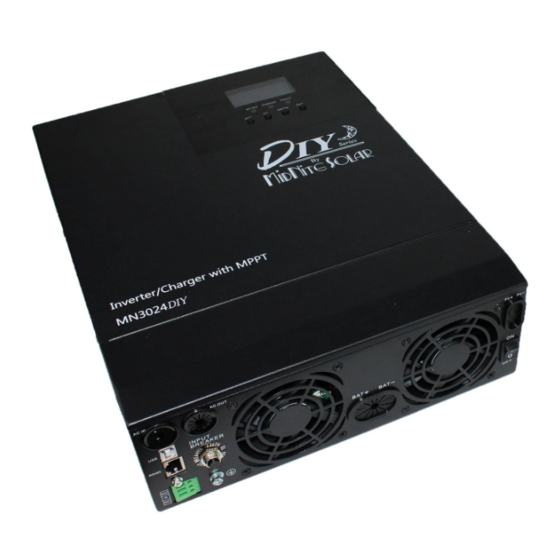
Page 6: Appearance
Battery port ⑩ ③ USB communication port ON/OFF rocker switch ④ RS485/CAN communication port PV port ⑤ Dry contact port Tou ch button ⑥ screw Grounding LED Indicator ⑦ AC input breaker LCD screen 10-527-1 MN3024DIY REV A 6 of 39... -
Page 7: Installation Instructions
The mains AC input and AC output are high voltage, so please do not touch the wiring terminals. Keep fingers and tools away from the fan, do not touch it to prevent injury. 10-527-1 MN3024DIY REV A 7 of 39... -
Page 8: Wiring Specificationsand Circuit Breaker Selection
Recommended Recommended circuit breaker Models Maximum PV PV wire size model number MN3024DIY 8 AWG MNEDC40 or MNEPV40 Note: The series string voltage shall not exceed the maximum PV input open circuit voltage. 10-527-1 MN3024DIY REV A 8 of 39... - Page 9 · Mounting for shunt · ETL listed for the USA and Canada · Bonded battery/inverter negative tie point · Equipment ground bus bar · compliment of conduit knock outs Dimensions: 17"H x 9"W x 3.5"D 10-527-1 MN3024DIY REV A 9 of 39...
- Page 10 Note: Breakers are there to protect the wire not the electronics. Select wire size for the application, and then select breakers for the wire size. All MidNite Solar breakers are rated for continuous duty. Recommended wire gauge and breaker size.
-
Page 11: Installation And Wiring
Refer to the installation diagram of the unit as above. Warning: Danger of explosion! Never install the MNS Hybrid Inverter and lead-acid batteries in the same confined space! Also do not install in a confined place where battery gas may collect. 10-527-1 MN3024DIY REV A 11 of 39... - Page 12 ① Prior to AC input/output wiring, disconnect the external circuit breaker and confirm that the wire used is the appropriate AWG. Please refer to Section 2.2 on pg. 8 “Wiring Specifications and Circuit Breaker ② Properly connect the AC input wire according to the wire Selection”; sequence and terminal position shown in the igure on the next page. Please connect the ground wire irst, and then the hot wire and then the neutral wire; 10-527-1 MN3024DIY REV A 12 of 39...
- Page 13 Note: The grounding wire shall be as large as possible ( N ot less than 10 AWG). The grounding point shall be as close as possible to the MNS Hybrid Inverter The shorter the grounding wire, the better. 10-527-1 MN3024DIY REV A 13 of 39...
- Page 14 ② Properly connect the BAT wire according to the wire sequence and terminal position shown in the figure on the next page. 10-527-1 MN3024DIY REV A 14 of 39...
- Page 15 Step 4: Check if the wiring is correct and tight. In particular, check if the battery polarity is reversed, if the PV input polarity is reversed and if the AC input is properly connected 10-527-1 MN3024DIY REV A 15 of 39...
- Page 16 After the load is stable, turn on the load with a small surge current. Note: If the MNS Hybrid Inverter does not work properly or the LCD indicator is abnormal, refer to Chapter 6 to handle the error. 10-527-1 MN3024DIY REV A 16 of 39...
-
Page 17: Operating Modes
4) Only Solar (Only Solar): Only PV charging, without Mains charging. This is the most energy efficient way in which the battery is charged, and is usually used in areas with good lighting conditions. 10-527-1 MN3024DIY REV A 17 of 39... -
Page 18: Output Mode
➣ Inverter priority mode: Switch to mains supply only when the battery is under voltage. This mode maximizes the use of DC power and is best suited for areas with a stable grid. 10-527-1 MN3024DIY REV A 18 of 39... -
Page 19: Lcd Screen Operating Instructions
Confirm /Enter Options under the settings menu, Indicators introduction Indicators Colors Description Steady on : M ains output AC/INV Yellow Flash: Inverter output Flash: Battery charging CHARGE Green Steady on : Charging completed FAULT Steady on : Fault state 10-527-1 MN3024DIY REV A 19 of 39... - Page 20 75%~100% . percentage is ≥ 75%. Indicates that the battery type of Indicates that the buzzer is not the machine is a lithium battery enabled 10-527-1 MN3024DIY REV A 20 of 39...
- Page 21 Indicates the grid supplying power to ③ ⑦ supplying power to the inverter the charging circuit circuit Indicates PV module supplying Indicates the inverter circuit ④ ⑧ power to the charging circuit supplying power to the load 10-527-1 MN3024DIY REV A 21 of 39...
-
Page 22: Setup Parameters Description
Then, press the “ENT” button to enter the parameter editing mode, and the value of the parameter is flashing. Adjust the value of the parameter with the “UP” and “DOWN” buttons. Finally, press the “ENT” button to complete the parameter editing and return to the parameter selection state. 10-527-1 MN3024DIY REV A 22 of 39... - Page 23 When the parameter [01] =SOL/SBU, the Utility to [05] 28.0V battery voltage is higher than the set value, and Battery Power default the output is switched from the mains to the Setpoint inverter. Setting range: 24V~ 30V. 10-527-1 MN3024DIY REV A 23 of 39...
- Page 24 7 [08] strings, default absorption charge voltage LF07/LF08/LF09 is 24.8V; for 8 strings, default absorption charge voltage is 28.4V; for 9 strings, default absorption charge voltage is 31.8V adjustable 10-527-1 MN3024DIY REV A 24 of 39...
- Page 25 , and the output is [14] 22V default voltage alarm not turned off; the setting range is 2 0V~ 26V, with a step of 0.2V. It is valid for user -defined battery and lithium battery . 10-527-1 MN3024DIY REV A 25 of 39...
- Page 26 50W, the inverter automatically restarts. Automatic restart when overload is disabled. If Restart when [23] DIS an overload occurs and the output is turned off, over load the unit will not restart . 10-527-1 MN3024DIY REV A 26 of 39...
- Page 27 After a low voltage shutdown the unit will restart undervoltage after the battery voltage reaches this setpoint. [35] 27V default recovery point Max PV charger [36] 60A default Max PV charger current. Setting range: 0~ 60A current 10-527-1 MN3024DIY REV A 27 of 39...
-
Page 28: Battery Type Parameters
Over - di scharge delay 1~30s time (Adjustable) 0~600 Equalizing charge minutes minutes minutes duration (Adjustable) Equalizing charge 0~250 days days days interval (Adjustable) 10~600 Absorption charge minutes minutes minutes minutes duration (Adjustable) 10-527-1 MN3024DIY REV A 28 of 39... - Page 29 (Adjustable) (Adjustable) (Adjustable) delay time 0~600 Equalizing charge minutes duration (Adjustable) 0~250 Equalizing days charge interval (Adjustable) 10~600 Absorption charge minutes minutes minutes minutes minutes minutes duration (Adjustable) (Adjustable) (Adjustable) (Adjustable) (Adjustable) (Adjustable) 10-527-1 MN3024DIY REV A 29 of 39...
-
Page 30: Other Functions
This is a USB communication port, which can be used for USB communication with the optional PC host software . To use this port, you should install the corresponding "USB to serial chip CH340T driver" and APP in the computer. 10-527-1 MN3024DIY REV A 30 of 39... -
Page 31: Protection
The unit will try again after three minutes. After five tries, the unit won’t Overload try again until the unit is powered down and restarted. protection Refer to the technical parameters table for information on settings. 10-527-1 MN3024DIY REV A 31 of 39... - Page 32 Battery input battery input fuse will blow reducing the risk of damage or fire. protection Charge short If a short circuit or an excessive overload occurs when charging the battery, charging will stop. protection 10-527-1 MN3024DIY REV A 32 of 39...
-
Page 33: Fault Code Meaning
Fan failure 【21 】 EEPROM Memory failure 【22 】 【23 】 ModelNumErr Model setting error Inverted AC Output Backfeed to Bypass AC RlyShort 【26 】 Input BusLow Internal battery boost circuit failure 【29 】 10-527-1 MN3024DIY REV A 33 of 39... -
Page 34: Troubleshooting
Use a multimeter to check if the PV input voltage exceeds the PV overvoltage maximum allowable input voltage rated . Check if the battery is not connected or if the battery circuit breaker Battery missing alarm is not closed. 10-527-1 MN3024DIY REV A 34 of 39... -
Page 35: System Maintenance
➣ MidNite Solar AKA MNS does not assume any liability for damage caused by: ① Improper use or improper installation, or location. (exposed to the elements) ② Open circuit voltage of the PV module exceeds the maximum allowable input voltage rating. -
Page 36: Technical Parameters
Rated output 3000 power (VA) Rated output 3000 power (W) Power factor Rated output 120Vac voltage (Vac) Output ± 5% voltage error Output 50Hz ± 0.3Hz frequency 60Hz ± 0.3Hz range (Hz) 10-527-1 MN3024DIY REV A 36 of 39... - Page 37 Circuit breaker specifications Overcharge Alarm and turn off charging after 1 minute protection PV charging Maximum PV open circuit 100Vdc voltage PV operating 30- 100Vdc voltage range MPPT voltage 30- 95Vdc range 10-527-1 MN3024DIY REV A 37 of 39...
- Page 38 5% to 95% (Conformal coating protection) range Noise ≤ 60dB Heat Forced air cooling, variable speed fan dissipation Communicati USB/RS485(Bluetooth/WiFi/GPRS)/Dry node control on interface Size (L*W*D) 378mm*280mm*103mm Weight (kg) All -in-one solar charge inverter 38 10-527-1 MN3024DIY REV A 38 of 39...
-
Page 39: Warranty
DIY breaker boxes and DIY accessories. At its option, MidNite Solar will repair or replace at no charge any MidNite product that proves to be defective within such warranty period. This warranty shall not apply if the MidNite Solar product has been damaged by unreasonable use, accident, negligence, service or modification by anyone other than MidNite Solar, or by...
Need help?
Do you have a question about the MN3024DIY and is the answer not in the manual?
Questions and answers