Table of Contents
Advertisement
STOP
STOP
Installation Instructions for Water Softeners
Includes Fleck 5600 and 2510 series valves
Thank You
Thank you for purchasing a new AFWFilters® Water Softener. We appreciate the opportunity
you have given us to provide you with better water. We are committed to providing the best
customer experience possible and have provided these installation instructions to make things
as simple as possible. If you have read through the instructions and FAQ section entirely and
still have questions, feel free to contact us for further help.
How To Use These Instructions
Since every installation is different we are unable
to address every possible situation that may arise.
That being said, these instructions are designed
as a general guideline for installation of your new
system. Installation will require a basic knowledge
of plumbing and plumbing connections. Pictures are
included to help identify common parts, compo-
nents, and connections, so what you have may vary
slightly from what is pictured. Please apply these
instructions with discretion and common sense.
For Questions or Troubleshooting
Most questions that arise are answered in this manual or the FAQ section at the end. If you
have read through this manual and the FAQ section and still have a question that has not
been answered, feel free to use the AFWFilters website to contact us.
DO NOT RETURN TO RESELLER!
Contact Us FIRST: help.afwfilters.com
For any questions, concerns, missing items, or problems contact us so
we can help. Resellers do not offer support or replacement parts.
that can have major impact on
tions will be shown here
A complete FAQ is at the end of this
manual
Page 1
This offers vital information
your system/install/experience
Tips, tricks, and recommenda-
Answers to common questions -
Advertisement
Table of Contents

Subscribe to Our Youtube Channel
Related Manuals for AFWFilters 5600 Series

Summary of Contents for AFWFilters 5600 Series
- Page 1 Includes Fleck 5600 and 2510 series valves Thank You Thank you for purchasing a new AFWFilters® Water Softener. We appreciate the opportunity you have given us to provide you with better water. We are committed to providing the best customer experience possible and have provided these installation instructions to make things as simple as possible.
-
Page 2: Before You Begin
Before You Begin We recommend thoroughly reading these instructions BEFORE you schedule a plumber or begin installation. This can reveal missing parts or other items that can save significant headache if caught before you begin. Basic plumbing skills are required for installation. If you are unsure of your abilities to install the system using these instructions please hire a qualified plumber. -
Page 3: All Systems
Systems may ship loaded, partially loaded, or unloaded. Loaded systems will have all the resin in the tank. Partially loaded systems will have some resin in the tank and some in one or more separate bags. Unloaded systems will have all the resin in separate bags and the tank will be very light (less than 30 pounds). - Page 4 Bypass Valve - Depending on your order your system will have either a single piece stainless steel bypass or a two part plastic bypass with yoke connection. This is what connects to your control head and provides standard fitting connections to hook up to your plumbing. Meter Assembly - The flow meter connects the control head and the bypass valve and it mea- sures the water flow to initiate regeneration on demand.
-
Page 5: Section 2: Preinstallation Preparation
Funnel (OPTIONAL) - The funnel is a complementary item that MAY be included with some unloaded systems to help fill the polyglass tank with the resin. If your system does not include one, a blender pitcher with the blade assembly removed will screw onto the tank and work well. Before You Start Plumbing Money-saving tip: If hiring a plumber to do the installation you can save some money by preparing the tank ahead of time. - Page 6 When filling the tank, do so slowly and ensure the If you have KDF media (heavy riser tube stays correctly positioned and centered in gold or brown media) it will be the tank. If you have more than one bag of resin the added to the top of the tank.
- Page 7 (Img Right) and connect it to the control head. NOTE: The 5600 series uses a brass fitting, while the 2510 series uses a plastic fitting. Step 4c: Connect brine line to brine tank Run the brine line through the hole in the side of the brine tank into the brine well with the float assembly.
- Page 8 the best results. You will need to add at least one bag of salt and can fill it up to the top of the brine well. Ensure there is salt in the brine tank at all times. The resin is precharged and able to treat the water out of the box.
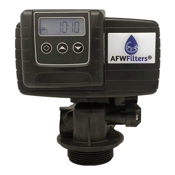
- Page 9 x1000 Indicator - Indicates current data display value is x1000. Programming Icon - Displayed when in programming mode. Service Icon - Indicates the system is in service (working). When flashing a regeneration will run at the programmed time. The service icon does NOT mean Error - When displayed an error code will be shown your system needs serviced.
- Page 10 You WILL need to adjust your capacity setting. DO NOT change any settings unless indicated here or directed to do so by an AFWFilters support technician. Other videos and instructions are not designed for AFWFilters systems and may lead to improper operation. If you change a setting in the MASTER programming that is not shown below use the system reset section to reset the system to defaults and adjust ONLY the settings shown below and in the USER programming section.
- Page 11 Setting Parameter Value Description Configures the system as a standard downflow Valve Type dF1b system with regeneration (salt) feed. Control Type Initiates the regeneration cycle based on water use. Capacity Varies Refer to Brine Fill/Capacity Settings chart below. Reserve Uses reserve capacity based on gallons. Selection Brine Fill Varies...
-
Page 12: Section 7: Plumbing Guidelines
SXT Resets Reset Directions Effect Soft Reset Hold Extra Cycle and Down This will reset all settings to default buttons for 25 seconds values, but leaves the volume remaining intact. Hard Reset Hold Extra Cycle button while This will reset everything in the system. plugging the unit in This should only be used if a soft reset does not work. - Page 13 After pushing the bypass and control valve together, The bypass valve will have tighten the screws to secure the clips and hold every- some up and down movement, this thing in place. is normal. Step 7b: Understanding the bypass valve The bypass valve on your system When installing the system allows for water to the system to be...
-
Page 14: Initial Startup
A physical air gap of at least 3 inches Drain water comes out under (76 mm) between the end of the line pressure, so it can be run ver- drain line and the wastewater level tically to connect to an overhead in the drain pipe should be used to drain pipe. - Page 15 is flowing correctly), or until any discoloration clears up. Depending on the system there may not be any discoloration, it may clear up almost immediately, or it may take a couple of hours. Once the water is cleared up a manual regeneration should be run. Step 8d: Initiate manual regeneration It is a good idea to allow the system to run through a manual cycle.
-
Page 16: Frequently Asked Questions
If you have a lot of sand in the water a spin down filter (part #SDF-100) is recommended to protect the control head - http://store.afwfilters.com/parts-components/ spin-down-sand-separator-filter-1-inch/. For water supplies with high levels of chlorine a car- bon prefilter is recommended to extend resin life. - Page 17 I am missing my drain line, where is it? Drain line is not included, since every installation is different and will require different lengths, styles, and sizes of drain line. I am missing my gravel, where is it? Most standard softeners do not require gravel, though fine mesh (Iron Pro) systems or very large systems will.
- Page 18 Does my system need gravel? Most standard softeners do not require gravel, though fine mesh (Iron Pro) systems or very large systems will. If your system requires gravel it will already be in the tank on loaded and partially loaded systems. If you believe your system should have gravel and you have an unloaded system without separate gravel you can contact us to see if you need it.
- Page 19 If everything else is connected and working correctly, the brine tank overflow should never come into play. The control head is designed to put a set amount of water in the tank, and should that fail for some reason, the float assembly will prevent the tank from overfilling. How much water should I add to the brine tank? None.
- Page 20 Digital Control Head Setup Will operating the control head without water damage it? No. The control head will operate fine with or without water flowing through it. Why does my display flashing between the time of day and a number? Is this an error code? This is normal, with the number displayed indicating the number of gallons until the next regeneration.
- Page 21 Unplug the system and check to en- sure all electrical connections and cam switches are secure. Plug the unit back in and check the master programming and Cycle Step Unexpected cycle ensure valve type and system type are Error input correct for your system.
- Page 22 Metered (Flow) Immediate - will regenerate imme- diately after programmed capacity is reached. Metered (Flow) Delayed - will regenerate at the preset time after programmed capacity is reached. Control Type Time Clock - will regenerate at the set regeneration time after the set number of days has passed. Day of the Week - will begin a regeneration cycle on the set day(s) at the set regeneration time.
- Page 23 To configure your brine fill time you need a couple things. The brine line flow control (BLFC) size (usually indicated by a sticker near the brine fitting) indicates the rate at which the brine tank is filled, 0.5 and 1.0 GPM are most common. You also need the size of your system in cubic feet of resin, and the salt dosage you want to use - 6 lb of salt per cubic foot of resin results in an efficient capacity of 21,000 grains per cubic foot, while 16 lb per cubic foot provides maximum capacity of 32,000 grains per cubic foot.
- Page 24 Can I run my drain line to a sewer/septic? Yes. These systems can be ran to your sewer or septic line and is typically the recommended place to run the drain. Most concerns are related to the amount of water going down the drain, and a properly designed septic/sewer system will not have a problem handling it.
Need help?
Do you have a question about the 5600 Series and is the answer not in the manual?
Questions and answers
We have a resin tank and a brine tank , which one girs first in line