Table of Contents
Advertisement
Quick Links
Advertisement
Table of Contents

Related Manuals for Loadrite Force


Summary of Contents for Loadrite Force
- Page 1 Weighing System OPERATORS MANUAL...
- Page 3 Please note that while every effort has been made to ensure that the data given in this document is accurate, the information, figures, illustrations, tables, specifications, and schematics contained herein are subject to change without notice. Actronic Ltd assumes no liability in connection with the use of any Loadrite branded product. © 2004 ACTRONIC LIMITED...
-
Page 5: Table Of Contents
Contents Loadrite Equipped Front-end Loader ................... 1 Introduction..........................2 Indicator Lights .............................. 3 Keypad ................................3 Quick Start Guide ........................5 Switching On ..............................5 Standby................................5 The Warm Up Screen ..........................5 The Ready Screen ............................6 Weighing a Load ............................6 Adding a Load ............................... - Page 6 12 Error Messages ........................37 Check Zero..............................37 Lift Under Range ............................37 Power Error..............................37 Printer Disabled ............................37 Printer Error ..............................37 Return Under Range...........................37 Too Heavy, Zero Aborted.........................38 Warm Up Lift..............................38 13 Specifications........................39 14 Output / Input Connections ....................41 Appendix i Time and Date ......................42 Appendix ii Span Calibration Adjustment................44...
-
Page 7: Loadrite Equipped Front-End Loader
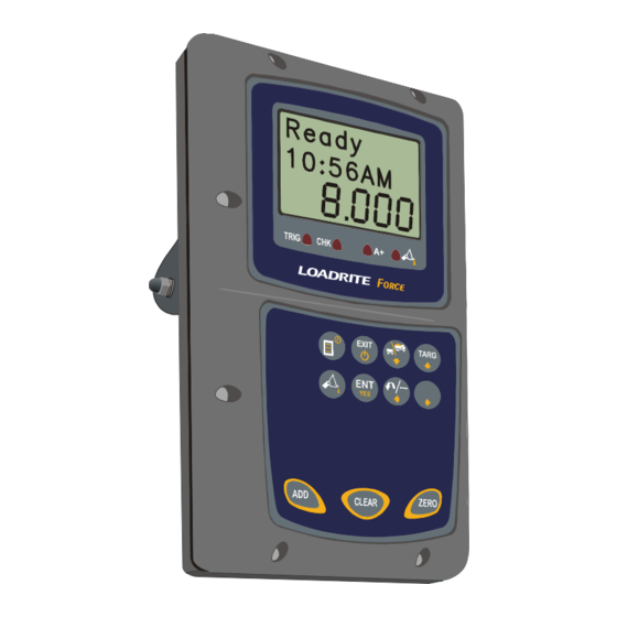
LOADRITE FORCE OPERATING MANUAL 1 Loadrite Equipped Front-end Loader 1. Indicator 2. Weigh trigger 3. Pressure transducers 4. Remote Add button (optional) 5. Printer (optional) -
Page 8: Introduction
The Loadrite Force Weighing System measures the weight of loads lifted by front-end loaders, log loaders, forklift trucks and similar machines that use hydraulic rams to lift the load. The Loadrite is installed in the cab of the loading machine and is connected to sensors on the lifting arms. -
Page 9: Indicator Lights
LOADRITE FORCE OPERATING MANUAL The Loadrite has internal memory which stores settings and production data even when switched off. Indicator Lights Four indicator lights are provided below the LCD screen. Trigger Tip-Off Auto-Add Check Trigger Illuminates when a load is lifted past the Pages 7 trigger point. - Page 10 LOADRITE FORCE OPERATING MANUAL Scroll down. Also enter Split Weigh mode. Page 24 Scroll up. Also enter Target mode. Page 21 Scroll left. Recalls the previous load. Subtracts Page 17 the current load from the total. Page 13 Scroll right.
-
Page 11: Quick Start Guide
Switching On The Loadrite powers up automatically when you switch on the ignition of the loading machine. If the Loadrite has been switched off for more than 1 hour, it displays the Warm Up screen when powered up. Standby The Loadrite has a ‘standby’ mode which is similar to turning the Loadrite off. -
Page 12: The Ready Screen
The Ready screen shows the product name and the short total for that product. The short total is simply the sum of loads since you last cleared the total. When the Ready screen is displayed, the Loadrite is in Total mode and is ready to weigh. R e a d y... -
Page 13: Adding A Load
Raise the load smoothly past the trigger T o t a l point using normal engine revs. 5600 2200 The Loadrite beeps and displays the load. (Weight of load 2200) R e a d y Press 0 2 : 4 0 P M... -
Page 14: Clearing The Short Total
R e a d y 0 2 : 4 0 P M Zeroing It is required to zero the Loadrite from time to time. This is to avoid inaccurate readings due to build up of material in the bucket. (Weights shown are examples only) - Page 15 LOADRITE FORCE OPERATING MANUAL Raise the bucket smoothly past the trigger T o t a l point. The Loadrite beeps and displays the load. R e a d y Press 0 2 : 4 0 P M The Loadrite performs the zero adjustment and returns to the Ready state.
-
Page 16: Weighing Overview
The normal mode of operation is Total mode, which uses the Ready screen. To return to Total mode from Target mode, press and hold Short and Long Totals The Loadrite keeps a total of the bucket weights that you add, of which two independent totals are stored. Short Total Typically used to display the total weight lifted onto a truck. -
Page 17: General Method Of Weighing
The Loadrite beeps, turns the TRIG light on and displays the load. (See also page 6). ADD. The Loadrite waits for a few seconds for you to take one of the following actions: •... -
Page 18: Weighing Procedures
Ready state. (New total 7800) The Loadrite has an option to use a remote add button. If fitted, the remote add button is normally mounted on the lift lever. The remote add button can be used instead of / as well as the add button on the keyboard. -
Page 19: Auto Add
Auto Add Auto Add is an optional feature that is selected during installation. If Auto Add is enabled, the Loadrite can automatically operate the ADD function every time a load is lifted past the trigger point. The Auto Add indicator light illuminates R e a d y when the Loadrite is in Auto-Add mode. -
Page 20: Zeroing
Raise the load smoothly past the trigger T o t a l point. 5600 2200 The Loadrite beeps and displays the load. (Weight of load 2200) R e a d y Press 0 2 : 4 0 P M 3400 The Loadrite updates the total and returns to the Ready state. - Page 21 If the weight is greater than 5% of full scale, when you press , the Loadrite prompts Bucket Empty? If it is, press ENT which will zero the empty bucket. Pressing EXIT will not zero the scale If the weight is greater than 10% of full scale, when you press...
- Page 22 Zeroing when Auto Add is On The procedure to zero may be different when Auto Add is on and Auto Add Time is set to 0. If this is how your Loadrite is configured, you will need to carry out the following procedure:...
-
Page 23: Recalling Last Load
(Weights shown are examples only) Current total 5600. R e a d y 0 2 : 4 0 P M 5600 Press The Loadrite beeps and displays the last T o t a l load. 5600 2200 (Weight of last load 2200) -
Page 24: Viewing Long Total
(Example: subtracting a load that was previously added, new total 3400) If you press a key that is not allowed in the circumstances, such as when the recalled load was previously added, the Loadrite ignores the key press. Viewing Long Total... - Page 25 23400 display the menu. to scroll to the Long Total option. Press The Loadrite displays the Long Total. L o n g T o t Press C l e a r ? The Loadrite asks you to confirm the clear...
- Page 26 LOADRITE FORCE OPERATING MANUAL R e a d y Press to confirm. 0 2 : 4 0 P M The Loadrite displays Long Tot Cleared for a few seconds and then returns to the Ready screen. Note that the Short Total is also cleared for...
-
Page 27: Target Mode
This feature provides an easy way to load up to a target weight for a product in a series of lifts. In Target mode, the Loadrite displays the “To Load” value, which is the remaining amount to reach the target. - Page 28 (Weights shown are examples only) T o L o a d 0 2 : 4 0 P M Press The Loadrite displays Target Reset for T a r g e t a few seconds and then … R e s e t …...
- Page 29 9000 T o t a l Press and hold M o d e The Loadrite displays Total Mode for a few seconds and then … … returns to Total mode. The message R e a d y Ready is shown along with the current 0 2 : 4 0 P M total.
-
Page 30: Split Mode
LOADRITE FORCE OPERATING MANUAL 7 Split Mode Split Mode is an optional feature that is selected during installation. This feature provides an easy way to load a truck with a trailer. You can split the total into multiple sub-totals. The following example illustrates how to use the split function. - Page 31 LOADRITE FORCE OPERATING MANUAL EXAMPLE (continued) TOTAL MODE TARGET MODE Add # 2: 5 000 T o L o a d T o L o a d 0 2 : 4 0 P M 0 2 : 4 0 P M The truck is full with a weight of 10 000.
- Page 32 LOADRITE FORCE OPERATING MANUAL EXAMPLE (continued) TOTAL MODE TARGET MODE Add # 4: 5 000 R e a d y T o L o a d (Next add towards the trailer). 20000 20000 This gives us: 10000 5000 Truck Total = 10 000...
-
Page 33: Tip Off
8 Tip Off This feature allows you to load a truck to an exact value by using only part of the last bucketful. There are two different methods, depending on the way the Loadrite has been set up: • Truck tip-off, or •... - Page 34 LOADRITE FORCE OPERATING MANUAL EXAMPLE (continued) TOTAL MODE TARGET MODE To tip off into truck a weight of 400kg: T r u c k Middle number shows total 5600 weight as it is being tipped onto the truck. Lower number shows weight tipped off onto the truck.
- Page 35 LOADRITE FORCE OPERATING MANUAL Stock Pile Tip-off Using this method, you dump product from the bucket until it contains the right amount for loading onto the truck. The following example illustrates the weigh screen shots when in Total Mode or Target Mode.
- Page 36 LOADRITE FORCE OPERATING MANUAL EXAMPLE (continued) TOTAL MODE TARGET MODE Roll the bucket partially forward, T o t a l T o t a l dumping product : 7500 -1500 1900 1900 with 300kg tipped off so far… The Loadrite displays the ‘live’...
-
Page 37: Menu Options
LOADRITE FORCE OPERATING MANUAL 9 Menu Options The Menu allows you to change some of the settings of the Loadrite. The options are as follows: Setup... Installation functions (security code required) Language Language setting Clock Clock setting Scale # Change scale... -
Page 38: Language Setting (Language)
LOADRITE FORCE OPERATING MANUAL Press to select. The Loadrite prompts you to enter an access code. For special functions, key in your security code and press Language Setting (Language) The Loadrite can optionally support multiple languages. If multiple language is enabled during installation, you can select the language in which the display texts will be shown. -
Page 39: Long Total (Long Tot)
Auto Add On/Off Setting (Auto Add) Auto Add is an optional feature that is selected during installation. If Auto- Add is enabled, the Loadrite can automatically operate the ADD function every time a load is lifted past the trigger point. -
Page 40: Uplink (Uplink)
Selftest. Press to select. Uplink (Uplink) Uplink mode is a special mode that communicates with a PC using Loadrite © Link (optional PC application). In this mode, you can use Loadrite Link to program product names and data list (customer list). -
Page 41: Print Functions
LOADRITE FORCE OPERATING MANUAL 10 Print Functions When a Loadrite printer is connected, weight data can be printed as you weigh loads. The print options are set up at installation time. The data can be automatically printed when particular functions are... -
Page 42: Obtaining The Best Accuracy
Lifting Speed The hydraulic pressure required to lift a load varies with the speed of lift. The Loadrite electronically corrects for most variations, but better accuracy is obtained if you limit the range of lifting speed used. Keep engine revs constant. -
Page 43: Error Messages
This indicates a fault in either the pressure transducer or the cable that connects the transducer. Power Error The Loadrite has detected that the power supply has dropped too low. Printer Disabled Print function has been disabled at installation. Printer Error The Loadrite has detected a fault in the printer. -
Page 44: Too Heavy, Zero Aborted
The Loadrite zero function can only zero up to 10% of full scale. See page 14 for details. Warm Up Lift This message appears if the Loadrite has been switched off for more than 1 hour. You need to lift the bucket/forks a few times to warm up. -
Page 45: Specifications
LOADRITE FORCE OPERATING MANUAL 13 Specifications Suitable Applications The Loadrite measures weight by sensing the hydraulic pressure required to lift a load. A trigger mechanism senses the position of the lifting arms. Typical vehicles using the Loadrite system are: • Front end loaders (bucket and/or fork) •... - Page 46 LOADRITE FORCE OPERATING MANUAL Display LCD display Back light Keypad 11 keys Back light. Special functions. Clock Hours, minutes, day, month, Built-in clock year. Physical Loadrite indicator Protected to IP54 Weight: 1.6kg Pressure transducer Protected to IP67 Position sensor Protected to IP67...
-
Page 47: Output / Input Connections
LOADRITE FORCE OPERATING MANUAL 14 Output / Input Connections Transducer +12V Return pressure input Transducer current input +10 volt excitation Lift pressure input Shield Ground Power/Control Negative supply (ground) Positive supply Remote button 2 (clear) Remote button 1 (add) N.C. -
Page 48: Appendix I Time And Date
To set the time and date: You may need an access code from your Loadrite Dealer to be able to set the clock. This is configured at installation time. A code is needed if the “Clock” function does not appear on the menu. - Page 49 LOADRITE FORCE OPERATING MANUAL The Loadrite displays the first of the time / T i m e date screens. 1 1 : 3 1 You can use to scroll through the time/ date screens. When on the required screen, press to change the setting.
-
Page 50: Appendix Ii Span Calibration Adjustment
Appendix ii Span Calibration Adjustment This function allows small changes to be made to the Loadrite calibration if the bucket or forks of the loader are modified or if no accurate test weight is available when the Loadrite is calibrated at installation time. - Page 51 Ready screen. Checking the Adjustment You can check the Calibration Adjustment by obtaining and comparing new Loadrite and Weighbridge Values. If necessary, the Calibration Adjustment can be performed again using the new data. Notes to remember: All trucks and trailers should have tare weights confirmed for all loads to be checked.
- Page 52 LOADRITE FORCE OPERATING MANUAL Index Accuracy ..............36 Print specifications ...........39 Functions ............35 Adding a load ............12 Printer Disabled - message .........37 Auto Add ..............13 Printer Error - message ........37 Bounce Ready screen............6 accuracy............36 Recalling last load..........17 Bucket Back Return Under Range - message......37 when weighing ..........11...