Table of Contents
Advertisement
Quick Links
Advertisement
Table of Contents

Related Manuals for OrionPC G03-JC610EN-F

Summary of Contents for OrionPC G03-JC610EN-F
- Page 1 User’s Manual G03-JC610EN-F Manual rersion: 2.0 Release Date:March, 2011...
-
Page 2: Package Contents
User’s Notice Copyright of this manual belongs to the manufacturer. No part of this manual, including the products and software described in it may be reproduced, transmitted or translated into any language in any form or by any means without written permission of the manufacturer. This manual contains all information required for the utilization of this product to meet the user’s requirements. - Page 3 Safety Instruction Operate the product according to the correct installation steps and with great care to make sure safety and comfort using experience. Please refer to the following safety instruction guide to avoid danger of electric shock or fire. Abide by the previous safety instruction guide to use and maintain the product and the hard disk to make sure of safe operating environment.
-
Page 4: Table Of Contents
TABLE OF CONTENT USER’S NOTICE ........................ii PACKAGE CONTENTS ......................ii SAFETY INSTRUCTION ......................iii CHAPTER 1 BRIEF INTRODUCTION PRODUCT FEATURES....................1 SPECIFICATION ......................4 FRONT PANEL DIAGRAM ..................5 REAR PANEL DIAGRAM ................... 5 CHAPTER 2 HARDWARE INSTALLATION TO OPEN THE CHASSIS ................... 6 TO INSTALL MEMORY MODULE(S)................. -
Page 5: Chapter 1 Brief Introduction
Chapter 1 Brief Introduction 1.1 Product Features Thank you for purchasing the system, a new product developed, designed and manufactured under leading technical power and consistent dedication to fine workmanship. The system provides you HTPC enjoyment and stunning game-playing experience. It can also serves as home server for data gather with its expandable Wi-Fi function. - Page 6 The system has the following features besides other basic functions: HDMI: The system comes with an HDMI output connector to realize full HD1080P high-definition multimedia home theatre enjoyment. User can enjoy seamless playback of HD DVD and Blu-ray disk in the living room by connecting system to LCD TV set with an HDMI cable for non-compressed, full digital audio and video movie transmission.
- Page 7 WiFi: the Mini PCI-E onboard socket in the board is integrated a with a WiFi card(802.11 b/g/n) that can act as a mini wireless modem when external antennas are connected. Different computers in the house can build wireless connections through the system and take necessary data from it, thus reducing the complexity in network establishment.
-
Page 8: Specification
1.2 Specification VIA Nano CPU Series VIA VX900H W/HDCP Chipset 2 * SO-DIMM DDRIII Memory slots support 2 * SO-DIMM DDRIII 800 Memory Slots memory modules up to 4GB Realtek Gigabit LAN chip Ethernet LAN AMI 8MB flash ROM Bios 205(W)*185(D)*30(H)mm Product Size 2 * USB 2.0 ports... -
Page 9: Front Panel Diagram
1.3 Front Panel Diagram USB Connectors Remote Sensor Power Switch W /Power LED Card Reader Slot Line-out /Optical SPDIF out shared connector 1.4 Rear Panel Diagram RJ-45 LAN Antenna Hole DC12V Jack HDMI USB Connectors Connector Connector E-SATA/USB Connector... -
Page 10: Chapter 2 Hardware Installation
Chapter 2 Hardware Installation WARNING! Please turn off the system and make sure that power cord is unplugged before hardware installation to ensure safety. 2.1 To Open the Chassis Place the system on a flat surface and put the Push the removable panel in the direction side with removable cover upwards. -
Page 11: To Install Memory Module(S)
2.2 To Install Memory Module(s) 1. Locate the SO-DIMM memory slot(s) on the board. Insert the gold-figure side of the compatible Press down as the photo shows. The eject DDRIII SO-DIMM into the slot at a 30 tabs will lock it if installed correctly. degree. -
Page 12: To Install Hard Disk Drive
Notice: When installing, align the notch on the module matches the break on the slot. Memory module can only be installed in such a direction. If not, it will cause serious damage to module and the board. When you install memory module fully into the DIMM socket the eject tab should be locked into the module very firmly and fit into its indention on both sides. - Page 13 Lock the SATA hard disk to one of the racks Lock the SATA hard disk to the other rack by by tightening the screws in the marked tightening the screws in the marked position. position. Fit the hard disk into HDD connector on the Lock the racks to the board by tightening up motherboard in this direction.
-
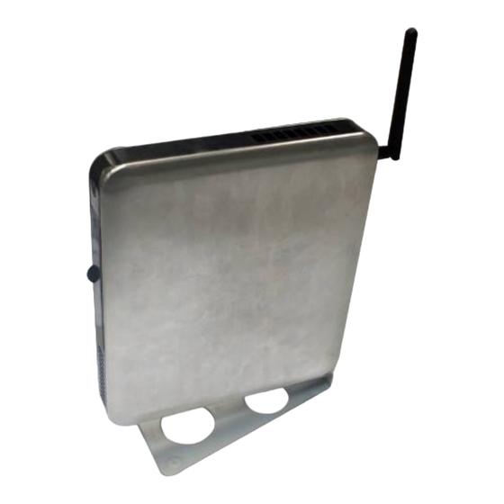
Page 14: To Install Wifi Antenna
2.4 To Install WIFI Antenna Locate the marked antenna hole on back Then connect the external WiFi receiver panel. antenna to it. 2.5 To Restore Removable Chassis Cover Gently put the removable cover back to This edge with 3 plastic equidistant notches the chassis should be parallel to edge of the chassis’... - Page 15 Front Panel Back Panel Place the removable cover upon the chassis. See to it that the left and right edges of the cover should be parallel to those of the chassis and there should be a distance of about 1 cm left between the front edge and the front panel of the chassis as the photo shows.
-
Page 16: To Assemble The Stand
2.6 To Assemble the Stand See to it that the marked square space See to it that the marked tiny round space and fitted into the square notch on the chassis. the screw hole in on the chassis are in the same place. -
Page 17: To Vesa Mount The System
2.7 To VESA Mount the System Attach the chassis rack to the back of monitor by See to it that the square notch on the tightening up the screws in the marked position. chassis is fitted into the marked square space on the stand and marked notch on the back panel of the chassis fitted in the round space of the VESA mount... - Page 18 The square notch on the chassis and the Lock the chassis to the rack by tightening up square space on the stand. the screw in the marked position.
-
Page 19: Chapter 3 I/O Connection And Remote Control
Chapter 3 I/O Connection and Remote Control After needed hardware installed inside the chassis, you can proceed on to connect cables to the rear panel and power on the system. 3.1 Rear Panel Connection USB Connector: There are 3*USB connectors on rear IO panel (one is USB/E-SATA shared connector that functions according to device connected) and 2*USB connectors on the front panel to connect USB mouse, keyboard and other USB storage devices to the system. - Page 20 USB/E-SATA Shared Connector: The function of this connector depends on different device connected to this connector through different cable. It could function as: E-SATA connector when a compatible ESATA hard disk is connected to it through SATA cable. USB connector when a compatible USB device is connected to it through USB cable. VGA Connector: VGA connector is the 15-pin D-sub female connector;...
- Page 21 HDMI (High-Definition Multimedia Interface): This point-to-point interface is for audio and video signals designed as a single-cable solution for home theater and consumer electronics equipment. DC12V Jack: Connect the power adapter to DC12V jack after connecting connector power cord to adapter.
-
Page 22: Front Panel Connection
3.2 Front Panel Connection Remote Sensor Power on Switch W/ Power LED MIC Connector Line-out/SPDIF_Out shared Connector USB Connectors Card Reader Slot Card Reader Slot: to insert the MMC/SD/MS card to the front 3 in 1 card reader. USB Connectors: to connect USB mouse, keyboard and other USB storage devices to the system. Line-Out /Optical SPDIF out shared Connector: this connector can function as ordinary audio line-out connector or optical SPDIF out connector depending on different device connected to it: Audio Line-out connector: by connecting stereo speakers or headphones. -
Page 23: Notices
Notices General Notices European Union CE Marking and Compliance Notices Products intended for sale within the European Union are marked with the Conformity European (CE) Making, which indicates compliance with the applicable Directive and European standards and amendments identified. Shielded Cables Notice All connections to other computing devices must be made using shielded cables to maintain compliance with FCC regulations. - Page 24 for use by consumers. These standards and recommendations reflect the consensus of the scientific community and result from deliberations of panels and committees of scientists who continually review and interpret the extensive research literature. In some situation or environment, the use of Wireless LAN PCI Express Mini Card may be restricted by the proprietor of the building or responsible representatives of the organization.
- Page 25 equipment. FCC Rules and Regulations-Part 15 This devices uses, generates and radiates radio frequency energy. The radio frequency energy produced by this device is well below the maximum exposure allowed by the Federal Communications Commission (FCC) This device complies with the limits for the Class B digital device pursuant to Part 15 subject to the following two conditions: This device may not cause harmful interference.
Need help?
Do you have a question about the G03-JC610EN-F and is the answer not in the manual?
Questions and answers