Table of Contents
Advertisement
Quick Links
Instruction Manual
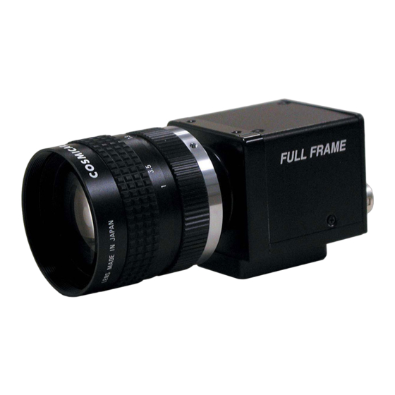
1.45Mega pixel Progressive Scan Monochrome Camera
● We greatly appreciate your confidence choosing our TAKEX CCD Video Camera.
● Please read this manual and the attached guarantee certificate carefully and manage the camera properly.
Keep this manual at hand and reread it whenever you are uncertain about the operation.
Video Camera
FC1600FPL
Table of Contents
......................................................... 3
.........................................................3
......................................................... 4
......................................................... 6
......................................................... 11
......................................................... 14
......................................................... 23
......................................................... 29
.........................................................33
......................................................... 33
......................................................... 34
TAKENAKA SYSTEM CO., LTD.
Document No. N11823
FC1600FPL Instruction Manual (7
- 1 -
K11823;1/34
th
Version)
Advertisement
Table of Contents

Related Manuals for Takex PoCL FC1600FPL

Summary of Contents for Takex PoCL FC1600FPL
-
Page 1: Table Of Contents
1.45Mega pixel Progressive Scan Monochrome Camera FC1600FPL ● We greatly appreciate your confidence choosing our TAKEX CCD Video Camera. ● Please read this manual and the attached guarantee certificate carefully and manage the camera properly. Keep this manual at hand and reread it whenever you are uncertain about the operation. - Page 2 K11823;2/34 [Revision history] Version Revised contents Articles Date Remarks Document No. version First edition- 2008-02-08 N08208 FC1600FPL version Added descriptive sentence 2008-04-04 N08208 version Error correction 2008-04-10 N08208 version Error correction Outline dimensional drawing 2009-10-29 N08A29 version Error correction 2009-01-23 N09123 Default 8bit →...
-
Page 3: Features
K11823;3/34 1. Features FC1600FPL is a full frame shutter camera incorporated with 1.45 megapixel, 2/3”-size, CCD image sensor ● A full frame shutter image can be obtained at 30 fps frame rate. ● Power delivery, image data transmission and camera control are performed using single cable by adopting Power over ●... -
Page 4: Description Of Each Component
K11823;4/34 3. Description of Each Component Shutter switch (3-1) Description of rear panel of camera Operation indicator Mode switch Panel to set up operation mode, electronic shutter speed and other parameters and to connect each output connector EXP. MO DE U... - Page 5 K11823;5/34 [Table of Camera Link bit assignment] (showing correspondence relation between before and after encoding) Camera Link port Camera signal Remark (Node name) name Strobe Pixel clock LVAL Horizontal synchronous timing FVAL Vertical synchronous timing DVAL (Fixed to H level) Spare (Fixed to H level) PORTA0 / PORTB0...
-
Page 6: How To Operate
K11823;6/34 FC 1 60 0 FP L P o CL mi ni Ca mer a L in k c ab le 4. How to Operate F UL L F RAM E (4-1) Connection method ● Connection S trob e s ign al ←... - Page 7 K11823;7/34 (4-2) Input of Vinit signal (asynchronous trigger signal) ● How to input Vinit signal If the camera is used in the asynchronous shutter mode, the Vinit signal (asynchronous trigger signal) must be input from the user side unit. The Vinit signal is input from Pin (4) of the “I/O” connector (6 pin connector) on the rear of the camera, or is input as the CC1 signal from the “Camera Link”...
- Page 8 K11823;8/34 ● Example of drive circuit for Vinit1 input circuit Inside of camera Vinit1 IN 3.3V [Example of user circuit] 3.3V TC74LVX14 4.7k VC C (or equivalent) Camera connector 74AC04 or To internal circuit 3.9 ZD others NORMAL VCC is +5V or +3V CC1 (Vinit2) input Setting of Vinit2 polarity INVERTED...
- Page 9 K11823;9/34 (4-5) Test pattern display function When initially connecting this camera to an image capture board, the use of the test pattern display function of the equipment makes it easier to confirm that the output timing of the camera and the details of the signal connection match the particulars of the capture board.
- Page 10 K11823;10/34 [Conversion method from returned data to temperature in Celsius] The temperature in Celsius is computed as Tc from the following formula where Dt is the signed integer number converted from the above described 10 bit binary value of “Db=B’D9D8…D0”: Internal temperature of camera: Tc=Dt×0.5°...
-
Page 11: Various Settings
K11823;11/34 5. Various Settings (5-1) Operation mode Electroni c shutter operation mode ● CCD output Single output Shutter ・・・・・ swi tch = 0 Shutter switch = 1 to 9 (Single line output) No shutter Elec tr onic shutter ● Electronic shutter operation mode oper ation operation Shutter mode... - Page 12 K11823;12/34 (5-2) Setting of shutter speed The shutter speed is determined mainly by the shutter switch position from “0” to “9”. When a shutter speed is specified using a communication command, the communication command is prioritized. The shutter speed to be displayed is the one that is corresponding to the currently selected shutter switch position. When “7”...
- Page 13 K11823;13/34 ● Correlation between MGC gain setting value and MGC gain The MGC setting value of this equipment is controlled by giving 24 to 224. The correlation between this setting value and the MGC gain (integrated gain including the gain of the variable gain amplifier and that of the fixed gain amplifier) is shown in the right graph.
-
Page 14: How To Change Settings
K11823;14/34 6. How to Change Setting (6-1) How to set shutter speed The shutter speed is determined mainly by the setting positions of the shutter switch from “0” to “9”. Table 6-1 Setting value of shutter speed Position of High speed shutter (continuous/asynchronous) Low speed shutter (continuous) shutter switch No shutter (continuous) - Page 15 K11823;15/34 Table 6-2 Start-up condition for each setting Group Start-up condition (at time of power-on) The groups of Operation Operation state of camera at Mode Setting start-up Position of mode switch UP/DOWN switch Arbitrary position Neutral position By normal automatic loading ( → Group 1 from 0 to F (no switch manipulation)
- Page 16 K11823;16/34 (6-3) Setting of program page The setting operations for the program pages are roughly divided into 2 groups: save (writing the current setting into the program page) and load (reading out the setting that was previously saved in the program page as the current setting). More specifically, “save”...
- Page 17 K11823;17/34 (6-4) Description of menu display by OSD (On Screen Display) This camera is equipped with the OSD function of superimposing a character information on the output digital image signal. Using this function, the current setting status of the camera can be displayed over the image of the capture board in menu-driven form.
- Page 18 K11823;18/34 S.FORM: The current shutter operation mode is displayed. The left is either MENU2 continuous (NORMAL) or asynchronous (ASYNC), and the right is MENU : ON either high speed (HIGH) or low speed (LOW). : (Reserved) : (Reserved) SCAN: The current scanning system is displayed. It is either all pixel : DISABLED readout scan (NORMAL) or partial readout scan (PARTIAL).
- Page 19 K11823;19/34 When a stroke is applied to the UP/DOWN switch, the value of gain or others increases or decreases by 1. When a stroke is applied and kept for about 2 seconds, the number continuously increases or decreases at fast speed after the response sound of “pip-pip”.
- Page 20 K11823;20/34 The items marked with <* 1> can not be changed by the communication command. [Description of FR data] Bit Abbrev Content Logic Remark 0 ASYE Selection of continuous/asynchronous shutter 1: Asynchronous (ASYNC) 1 PWCE Selection of enabled/disabled for pulse width 1: Enabled pulse width control control 2 LEXE...
- Page 21 K11823;21/34 (6-7) Typical setting procedure (Example 1) This is the procedure for setting the gain for the START asynchronous shutter operation (1/250 sec.). Turn on power. [Explanation] Be ready for switching between The left example of the setting procedure is for using the Set mode switch to “5”.
- Page 22 K11823;22/34 Read out of factory default (6-8) Setting items to be read out to RAM This procedure is for reading out the factory default (initial setting [Electronic shutter operation mode] before shipment) in order to initialize the setting that was changed •...
-
Page 23: Serial Communication Control
K11823;23/34 7. Serial Communication Control FC1600FPL can be externally controlled by serial communication via Camera Link. (Note) When the operation modes of the camera are changed by the communication functions, it takes some time to switch the modes. Carefully note that normal image may not be obtained from the signal for each one frame before and after transmitting a command. - Page 24 K11823;24/34 4) Shutter mode report Transmission from host: STX: “R”: “S”: ETX □ □ □ Return by camera: STX: ACK: “R”: “ ” * : “ ” * : “ ” * : Exposure time * : ETX 1 to 3 : Refer to (4) command “S”...
- Page 25 K11823;25/34 (Note) When directly specifying the exposure time, only the following range of values is acceptable. The operation with other values than these is not guaranteed. Normal scan: H’0000 to H’01EC (D’0 to 492) (“0” is used only when the external specification is cancelled.) Partial scan: H’0000 to H’00A9 (D’0 to 169) (“0”...
- Page 26 K11823;26/34 (12) Command “RMF” Function: Command for reading mode flag register (FR) (Read Mode Flag) Transmission from host: STX: “RMF”: ETX Return by camera: STX: ACK: “RMF”: flag setting value: ETX (transaction completion), or STX: NAK: ETX (transaction rejection) The current content of the mode flag register (2 bytes/4 characters) is returned in the hexadecimal system. (13) Command “SMC”...
- Page 27 K11823;27/34 The acceptable characters are English 1 byte characters (both upper and lower cases) and some special symbols as shown below: Usable special symbols······ SP(H'20), !(H'21), ’(H'27), +(H'2B), comma (H'2C), -(H'2D), .(a full stop mark)(H'2E), /(H'2F), : (H'3A), ;(H'3B), <(H'3C), =(H'3D), >(H'3E), ?(H'3F), [(H'5B)], (H'5D), _ (H'5F) (Note) When the number of the characters exceeds 15, (transaction rejection) is returned.
- Page 28 Takenaka’s free software ”FCTool” is available to set parameters inside the camera via serial communication at the time of product evaluation or initial setting. It is free to download FCTool from the website of TAKENAKA SYSTEM Co.,Ltd. http://www.takex-system.co.jp/ - 28 -...
-
Page 29: Timing Chart
K11823;29/34 8. Timing Chart ● Pixel clock timing (common in various operation modes) [Phase relationship between clock output and data] DEMULTIPLEX. Camera Link 1CLK=33.3nS connector 10/8bit 10bit Clock output 10/8bit 10ns (max) Digital data (LDV, FDV) CH1: 10bit CH2:10bit PCLK (Note) The above timing represents the signal timing before being encoded to serial data by the channel link device on the side of the sending end (the part circled in the above right figure). - Page 30 K11823;30/34 ● Vertical timing: Continuous shutter 1Ve rti cal per iod ( 1 V) = 1fr ame tim e 1 06 8 ;Nor mal sc an 9 53 4 ;Par tia l s can VD ( I nter na lv ertica l )...
- Page 31 K11823;31/34 ● Vertical timing: High speed/pulse width control/asynchronous shutter/normal scan m Vin it HD (I n te r n al ho rizon tal ) synch sign al (SG) End of expos ure (mH) E xpos uretim e (mH) E xposure time STR...
- Page 32 K11823;32/34 ● Vertical timing: High speed /preset shutter/ asynchronous shutter /normal scan/ with H-Reset Vin it 42 ~ 43 C L K HD I n t e rn a l h o r i zo n t a l s yn c s ig n a l End of exposure(SG) 10...
-
Page 33: Notes
K11823;33/34 9. Notes ● More stable image (suitable for highly accurate measurement) can be obtained by leaving the equipment for 20 or 30 minutes after the power is turned on. ● A longer exposure time in the pulse width control mode is accompanied by the degradation of S/N ratio due to a decrease in the dynamic range of CCD, accumulation of thermal noise components of the CCD imaging device in proportion to the exposure time. -
Page 34: Dimensions
K11823;34/34 11. External Dimensions [External dimensions] 9 .2 E XP . MO DE C am e ra Li n k I /O 2×2-M3 Depth6 (Right and left sides) Depth4 2×2-M3 Depth6 (Same as top side) 2-M6 Depth7 1/4”-20UNC Depth7 1 3. 5 Fig.11-1 FC1600FPL external views - 34 -...
Need help?
Do you have a question about the PoCL FC1600FPL and is the answer not in the manual?
Questions and answers