Table of Contents
Advertisement
Quick Links
FL-10 Operation Manual
CONTENTS
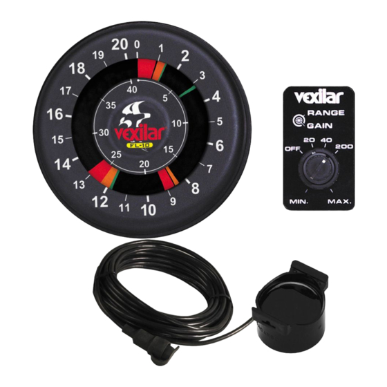
General Description
Specifications
Unit Installation
Transducer Installation
Unit Operation
Helpful Tips
Trouble Shooting Chart
About Transducer Beam Angles
Other Vexilar Products
Transducers
Service and Support
Founded in 1960, Vexilar, Inc. has a
long history of bringing revolutionary
technology to the sport fishing industry.
Just some of the Vexilar firsts include: the
first liquid crystal display, the first fish
alarm, the first three color display, and
the first CRT and straight line paper
graphs for the sport fisherman.
1
2
3
4 - 5
6 - 9
10 - 15
16
17
18 - 19
20 - 21
22 - 22
24
Advertisement
Table of Contents

Subscribe to Our Youtube Channel
Related Manuals for VEXILAR FL-10


Summary of Contents for VEXILAR FL-10
- Page 1 Founded in 1960, Vexilar, Inc. has a long history of bringing revolutionary technology to the sport fishing industry. Just some of the Vexilar firsts include: the first liquid crystal display, the first fish alarm, the first three color display, and the first CRT and straight line paper graphs for the sport fisherman.
-
Page 2: General Description
These "sound" pulses radiate from the transducer downward and are reflected back up to the transducer where the energy is converted back to electrical signals. The FL-10 then processes these signals and displays them. The circular display is accomplished by attaching an LED (Light Emitting Diode) to a wheel, which is then spun at a high speed in the clockwise direction. -
Page 3: Specifications
Weight: 2-1/2 Lbs. w/transducer Transducer Beam Angle: Puck Style - 12 Degree Transom Mount - 12 Degree Additional beam angle options are available. See page 22 Dimensions The FL-10 is designed to fit in a 3-3/8” to 3 1/2” hole. -
Page 4: Unit Installation
UNIT INSTALLATION To install the unit refer to Figure 4. You must have a minimum 3-3/8" hole in your dash or panel. Also, within 12", you should dedicate space for a 3/8" hole for the control and decal. Make sure that you will have enough room behind the dash to accept the unit and control. - Page 5 panel. Ideally you want the outside nut to be as close to the outer end of the shaft as possible. When the right spacing has been achieved tighten snugly into place. Make sure the inner shaft portion is rotated fully counter-clockwise and then place the larger rubber o-ring fol- lowed by the larger control knob onto the shaft.
- Page 6 PUCK TRANSDUCER MOUNTING To attach a puck style transducer to a trolling motor use the large cable tie provided. Notice the slots in the transducer for this purpose. Locate the transducer on the bottom of the lower unit (figure 5). Run the cable up the shaft using smaller cable ties to hold it in position.
- Page 7 After the boat is launched, put about a half inch of water in the bilge and set the transducer into the the water. Moving it even an inch in any direction can effect the quality of the reading drastically. Move it around until you get the best reading.
-
Page 8: Transom Transducer Installation
TRANSOM TRANSDUCER MOUNTING Locate the transducer, and bracket hardware. This includes; 1 - Transducer 2 - Angle Brackets 4 - Bracket Screws 2 - Bracket Plates 4 - Nuts 4 - Mounting Screws First, attach the bracket to the transducer as shown in Figure 7. - Page 9 water. Ideally, Figure 7 transducer should be just under the bottom of the boat. However, you may need to lower it 1/2” to 5/8”, depending on your hull shape, to get a good reading at top speed. Drill out the holes and tighten the bracket to the hull securely.
-
Page 10: Unit Operation
UNIT OPERATION To switch the FL-10 on, turn the larger control knob to the right. Turning the unit on also selects the depth range. The first setting covers zero to 20 feet. The second range covers 0 to 40 feet and the third range covers 0 to 200 feet. If the first setting shows only a mark at the zero position on the display, switch to a deeper range until you see the depth mark appear. - Page 11 The three-color display on the FL-10 will give you a lot more information than just depth. A color represents the strength of a signal. A red color indicates a strong signal, an orange color indicated a medium strength signal, and green represents a weak signal.
- Page 12 Figure. J ZERO MARK SURFACE CLUTTER TRAILING EDGE BAIT FISH BOTTOM PLANKTON SIGNAL LEADING EDGE Read Depth Here FISH ZERO MARK Figure. K SURFACE CLUTTER TRAILING WEED TOPS EDGE BOTTOM SIGNAL LEADING EDGE Read Depth Here WEEDS POSSIBLE FISH...
- Page 13 SEEING FISH The FL-10 sees a fish as a target, much like the bottom. It has a leading edge, a width, and color content. Refer again to figure J. If the range control is set to the 20 foot scale, then the fish is just over three feet above the bottom.
- Page 14 The FL-10’s internal circuitry will block out most noise, but sometimes, extra measures are required to eliminate it. Please contact our service department or log on to www.vexilar.com for more information.
- Page 15 NAVIGATION Although the FL-10 can give you a very fast update of depth information, use common sense when navigating. Even though you can see the depth get shallow fast, you may not be able to react fast enough to avoid danger.
-
Page 16: Helpful Tips
Usually a simple grounding wire connected between the negative trolling motor lead and the negative starting battery post will eliminate any noise. Use an 18 gauge wire with a 1 amp fuse. Contact Vexilar service or log on to www.vexilar.com for more information. -
Page 17: Troubleshooting Chart
Everything is working That is why they call it “fishing” and not great, but cannot catch “catching”. We here at Vexilar experience any fish. this often. --- Just have fun. - Page 18 ABOUT TRANSDUCER BEAM ANGLES Beam angle has a large effect on the performance of your depth finder. There is more to it than simply area of cover- age. The correct beam angle to use depends entirely on what you are trying to do with your sonar. If you are fishing for suspended fish then you probably would be very pleased with the performance of a 19º.
- Page 19 A nar- row beam transducer can be overpowering in shallow water. The FL-10 In-Dash comes standard with the 12 degree angle. This beam angle that works well in most applications.
- Page 20 The FL-8SE The FL-8SE has the same great features as your FL-10 In-Dash, plus six depth ranges and an enhanced interference rejection system that allows it to run cleanly right next to another depth finder.
- Page 21 The CLC-200 Five-Color LCD The CLC-200 is an affordable five-color liquid crystal depth/fish finder. This ultra- compact unit is available in a super portable Boundary Waters version (shown) or in a standard gimbal mount setup complete with a Pro Mount removable swivel bracket.
- Page 22 Transducers and Accessories TB0044 - 19° transom mount high Speed Transducer. Comes with the mounting bracket and 25 feet of cable. TB0030 - 9° transom mount high speed transducer. Comes with the mounting bracket and 25 feet of cable. TB0084 - 12° transom mount high speed transducer. Comes with the mounting bracket and 25 feet of cable.
- Page 23 If you are finding that the FL-10’s gain control is set to minimum, but you still have too much signal on the display, the S-Cable will help. Simple installation between the unit and transducer.
- Page 24 (952) 884-5291 (8 am to 5 pm M-F Central Time) (952) 884-5292 Email service@vexilar.com Web Site www.vexilar.com The Vexilar web site contains a wealth of helpful information. Plus, you can register your warranty, find transducers, accessories, additional product information, and even download lost manuals.
Need help?
Do you have a question about the FL-10 and is the answer not in the manual?
Questions and answers