Table of Contents
Advertisement
Quick Links
KSZ8081RNA / KSZ8081RND
10Base-T/100Base-TX
Physical Layer Transceiver
Evaluation Board User's Guide
Revision 1.0 / August 2012
© Micrel, Inc. 2012
All rights reserved
Micrel is a registered trademark of Micrel and its subsidiaries in the
United States and certain other countries. All other trademarks are the
property of their respective owners.
The information furnished by Micrel in this datasheet is believed to be accurate and reliable. However, no responsibility is
assumed by Micrel for its use. Micrel reserves the right to change circuitry and specifications at any time without
notification to the customer. Micrel Products are not designed or authorized for use as components in life support
appliances, devices or systems where malfunction of a product can reasonably be expected to result in personal injury.
Life support devices or systems are devices or systems that (a) are intended for surgical implant into the body or (b)
support or sustain life, and whose failure to perform can be reasonably expected to result in a significant injury to the user.
A Purchaser's use or sale of Micrel Products for use in life support appliances, devices or systems is at Purchaser's own
risk and Purchaser agrees to fully indemnify Micrel for any damages resulting from such use or sale.
Micrel, Inc. 2180 Fortune Drive San Jose, CA 95131 U.S.A.
408-944-0800 (voice) 408-474-1000 (fax)
http://www.Micrel.com
Advertisement
Table of Contents

Subscribe to Our Youtube Channel
Related Manuals for Micrel KSZ8081RNA


Summary of Contents for Micrel KSZ8081RNA
- Page 1 A Purchaser's use or sale of Micrel Products for use in life support appliances, devices or systems is at Purchaser's own risk and Purchaser agrees to fully indemnify Micrel for any damages resulting from such use or sale.
- Page 2 KSZ8081RNA / KSZ8081RND 10Base-T/100Base-TX Evaluation Board User’s Guide Revision History Revision Date Summary of Changes 8/17/12 Initial Release Micrel, Inc. August 17, 2012 Rev. 1.0 2/11...
-
Page 3: Table Of Contents
KSZ8081RNA / KSZ8081RND 10Base-T/100Base-TX Evaluation Board User’s Guide Table of Contents Introduction ................5 Board Features ................ 5 Evaluation Kit Contents ............5 Hardware Description ............. 6 RMII (Reduced Media Independent Interface) ............7 ... - Page 4 KSZ8081RNA / KSZ8081RND 10Base-T/100Base-TX Evaluation Board User’s Guide List of Figures Figure 1. KSZ8081RNA / KSZ8081RND Evaluation Board ............6 Figure 2. KSZ8081RNA-EVAL interfacing with KSZ8463RLI Evaluation Board ......7 List of Tables Table 1. Board Configuration for RMII Clocking Modes ..............8 ...
-
Page 5: Introduction
The difference between the KSZ8081RNA and KSZ8081RND is the default clocking configuration for the RMII interface. The KSZ8081RNA (by default) outputs a 50 MHz RMII Reference clock, while the KSZ8081RND (by default) takes the 50 MHz RMII Reference clock as an input. -
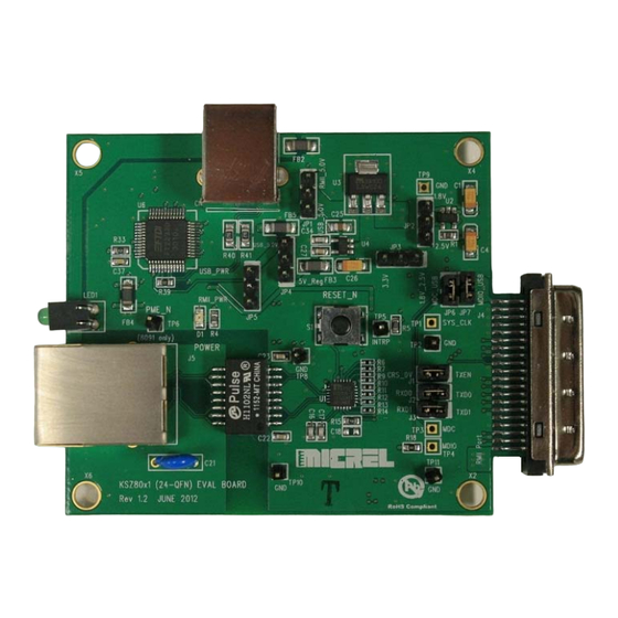
Page 6: Hardware Description
KSZ8081RNA / KSZ8081RND 10Base-T/100Base-TX Evaluation Board User’s Guide Hardware Description The KSZ8081RNA-EVAL / KSZ8081RND-EVAL (shown in Figure 1) come in a compact form factor and plugs directly into other boards with Ethernet MACs that expose the RMII interface through an MII connector. Configuration of the KSZ8081RNA / KSZ8081RND is accomplished through on-board jumper selections and/or by PHY register access via the MDC/MDIO management pins at the MII connector. -
Page 7: Rmii (Reduced Media Independent Interface)
Figure 2. KSZ8081RNA-EVAL interfacing with KSZ8463RLI Evaluation Board Two RMII clocking modes are available with the KSZ8081RNA and KSZ8081RND. The KSZ8081RNA powers up in RMII-25MHz Mode, while the KSZ8081RND powers up in RMII- 50MHz mode. After power-up, both KSZ8081RNA and KSZ8081RND can be programmed via PHY register 1Fh bit [7] to either 25MHz mode or 50MHz mode. -
Page 8: Table 1. Board Configuration For Rmii Clocking Modes
R11, C16, C17, Y1 Table 1. Board Configuration for RMII Clocking Modes The KSZ8081RNA-EVAL / KSZ8081RND-EVAL have provision for an oscillator in position Y2. This oscillator is normally not used, and is therefore not populated. If desired, a 25MHz oscillator (and appropriate resistor installation) may be used in place of oscillator Y1 for 25MHz Mode. -
Page 9: Mdc/Mdio Management Interface
MII connector J4. Also note that the MIIM (MDC and MDIO) signals of the KSZ8081RNA / KSZ8081RND operate at the VDDIO supply voltage, which is configurable as 3.3 / 2.5 / 1.8 V. When MIIM is accessed through the MII connector, the user must ensure that the voltage levels are compatible between the KSZ8081RNA / KSZ8081RND and the connected MAC device. -
Page 10: Rmii Loopback Jumpers
LED. A second voltage regulator optionally supplies reduced I/O voltage for the KSZ8081RNA / KSZ8081RND. The I/O voltage level of the KSZ8081RNA / KSZ8081RND can be set to one of three different levels. The jumper settings for these options are shown in Table 5. -
Page 11: Test Point Definition
KSZ8081RNA / KSZ8081RND 10Base-T/100Base-TX Evaluation Board User’s Guide 4.5 Test Point Definition The KSZ8081RNA-EVAL / KSZ8081RND-EVAL have several test points. They are defined in the following table. Test Point Definition SYS_CLK_BTB (50MHz Mode RMII clock, requires installation of R21) TP2, TP8, TP9, TP10, TP11...
Need help?
Do you have a question about the KSZ8081RNA and is the answer not in the manual?
Questions and answers