Table of Contents
Advertisement
Quick Links
Your Reliable Partner in Industrial IoT
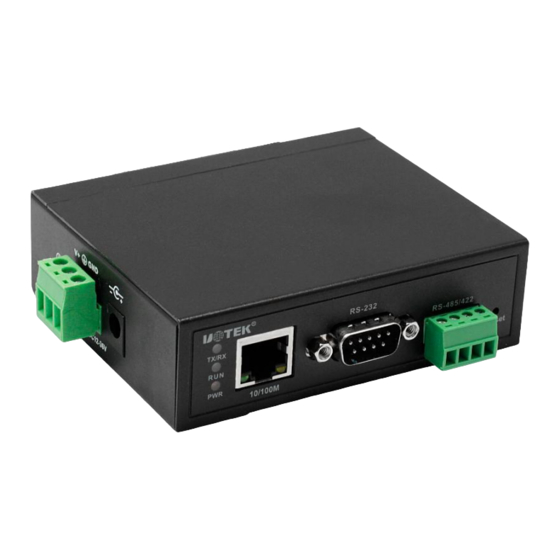
Serial Device Server
Product Manual
Model: UT-600X series
Sep 15, 2019
Version:V1.0
UTEK TECHNOLOGY (SHENZHEN) CO., LTD.
Add: Floor 8-10, Building 7, Skyworth Innovation Valley, No. 8, Tangtou No.1
Road, Shiyan Street, Shiyan Old Street, Bao 'an District, Shenzhen
Tel:+86-755-81202008
Fax:+86-755-27886083
Http:www.uotek.com
UTEK TECHNOLOGY
Page 1
Advertisement
Table of Contents

Related Manuals for UTEK UT-600 Series


Summary of Contents for UTEK UT-600 Series
- Page 1 Serial Device Server Product Manual Model: UT-600X series Sep 15, 2019 Version:V1.0 UTEK TECHNOLOGY (SHENZHEN) CO., LTD. Add: Floor 8-10, Building 7, Skyworth Innovation Valley, No. 8, Tangtou No.1 Road, Shiyan Street, Shiyan Old Street, Bao 'an District, Shenzhen Tel:+86-755-81202008 Fax:+86-755-27886083 Http:www.uotek.com...
-
Page 2: Table Of Contents
4.1 System Status ............................11 4.2 Serial Port Information ..........................12 4.3 Device & Language ........................... 12 4.3.1 Interface Description ..............................12 4.3.2 Time Setup ................................... 13 4.3.3 Console Setup ................................13 4.3.4 Ping ....................................15 UTEK TECHNOLOGY Page 2... - Page 3 TCP server mode .................... 32 13 Vcom Instruction ........................32 13.1 Remote Devices Management ....................... 33 13.1.1 Remote Devices Management ..........................33 13.1.2 Remove Device ................................34 13.1.3 Login ..................................35 13.1.4 Settings ..................................35 13.1.5 Assign IP ..................................38 UTEK TECHNOLOGY Page 3...
- Page 4 13.2.3 Modify COM ................................43 13.2.4 Enable COM ................................43 13.2.5 Disable COM ................................44 13.2.6 Import COM List ................................ 44 13.2.7 Export COM List ................................. 45 13.3 Options ..............................45 13.4 About ..............................45 13.5 Exit ................................46 UTEK TECHNOLOGY Page 4...
- Page 5 Your Reliable Partner in Industrial IoT Revision History Date Version Description 2019-09-15 V 1.0 UTEK TECHNOLOGY Page 5...
-
Page 6: Contents
Your Reliable Partner in Industrial IoT Preface Target Reader This manual is applicable to installers and system administrators responsible for installing, configuring or maintaining the network. This manual assumes that you know all the transmission and management protocols used by the network. This instruction also assumes that you are familiar with the professional terminology, theoretical principles, practical skills and specialized knowledge of network device, protocols and interfaces related to networking. -
Page 7: Overview
Has one or more (1,2,4,8) serial ports, can be connected with terminal, Modem, bar code machine, cash register, ISDN, terminal adapter, serial printer, PC and other serial control function; equipment, supports remote With reset button, press 1s, can restore to factory default within 5s when the UTEK TECHNOLOGY Page 2... -
Page 8: Software Feature
The management password can be set, and only the system administrator can manage the terminal server, so as to prevent unauthorized personnel from arbitrarily modifying UT-600X serial device server, and ensure the security of UT-600X. 1.3 Application Mode 1.3.1 Virtual Serial Port Mode (up to 256 serial ports) UTEK TECHNOLOGY Page 3... -
Page 9: Point To Point Mode
Your Reliable Partner in Industrial IoT 1.3.2 Point to Point Mode 1.3.3 Point to Multi-point Mode (Max. 4 clients) 1.3.4 Multi-host Mode (Max. 4 host) UTEK TECHNOLOGY Page 4... -
Page 10: Hardware Description
Power indicator 2.2 Serial Port Pin Assignment 2.2.1 UT-600X Serial Port PIN Assignment(RJ45) RJ45 RS-232 RS-485 HALF RS-422 FULL DATA+ TXD+ DATA- TXD- RXD+ RXD- 2.2.2 UT-600XMT PIN Assignement(RS-485/422) 3.81 terminal block RS-485 RS-422 T/R+ T/R- UTEK TECHNOLOGY Page 5... -
Page 11: Ut-600X 10/100M Ethernet Port Pin Assignment (Rj45)
For MDI-X port of serial device server, it adopts cross line: 1→3, 2→6, 3→1, 6→2. The 10Base-T/100Base-TX pin definitions in MDI/MDI-X applications are shown as below: MDI-X 4, 5, 7, 8 — — MDI-X: (Direct line) UTEK TECHNOLOGY Page 6... -
Page 12: Specification
ARP, IP, ICMP, UDP, TCP, HTTP, TELNET, DNS, DHCP Software Virtual COM Windows 2000/XP/7/8/10 32/64bit Working temperature -40 ~ 85°C Working humidity 5 ~ 95% Environment Storage temperature -40 ~ 85°C Storage humidity 5 ~ 95% Certificates FCC, CE Power UT-6001/UT-6002:DC12~36V、350mA@12Vmax(With optional for UTEK TECHNOLOGY Page 7... -
Page 13: Packing
1 set 1 set UT-6004-5V 1 set DC5V/2A 1 set 1 pc RS-232/485/422,RJ-45,5V power RS-485/422,3.81 terminal block output, UT-6004MT-5V 1 set DC5V/2A 1 set 5V power UT-6008 1 set DC12V/1A 1 set 1 pc RS-232/485/422,RJ-45 output UTEK TECHNOLOGY Page 8... -
Page 14: Login The Webpage
UTEK TECHNOLOGY Page 9... -
Page 15: Web Interface
Enable or disable Web & Telnet access PING Ping operation to the target device IP Accessible IP IP Limitation Network IPV4/IPV6 static & dynamic IP setting Port config Port config SNMP SNMP setting & trap function System maintance Change password Change password UTEK TECHNOLOGY Page 10... -
Page 16: Basic
Server name Device network identification Hardware version Current hardware version information Firmware version Current firmware version information System up time How long the device used Current time Show current PC time IP configuration Show IP configuration UTEK TECHNOLOGY Page 11... -
Page 17: Serial Port Information
Server name Menu language Select the language 3. Operation Steps Step 1. Click “Basic”, enter “Device setup” Step 2. Set the parameter, click “Apply” Step 3. If need to set it as default, click “save & reboot”-“Apply” UTEK TECHNOLOGY Page 12... -
Page 18: Time Setup
Users can check current Settings via web and Telnet login. When the TELNET service is enabled, the TELNET terminal can connect to the serial device server via the TELNET program on PC. Click the "basic>console setup" menu in the navigation to enter the interface. It is shown as below: Explanations UTEK TECHNOLOGY Page 13... - Page 19 If the above conditions are met, TELNET can be used to log in to the serial device server for configuration. 2. Example Before login the serial device server through Telnet, user needs to enter "Telnet+ space + product IP" for verification. Enter “enter” key at PC, it is shown as below: UTEK TECHNOLOGY Page 14...
-
Page 20: Ping
"ping" interface. It is shown as below: 5 Accessible IP 1. Interface Description It can set the access IP of the device and filter the access IP. The interface is shown as below: 2. Keyword Explanations UTEK TECHNOLOGY Page 15... -
Page 21: Ip Configuration
6 IP Configuration 1. Interface Description It can set the IP parameters. The interface is shown as below: 2. Keyword Explanations IP configuration Set the configuration mode IP address Set IP address Subnet mask Set subnet mask UTEK TECHNOLOGY Page 16... -
Page 22: Port Config
Serial port baud rate(it should be the same as the connected device) Data bits Default is 8, normally it should be the same as the connected device Parity Included None, Even, Odd, Mark, Space, default is N,normall it should be the same as the connected device UTEK TECHNOLOGY Page 17... -
Page 23: Working Mode
If the setting for all the ports are the same, check it Separator Set the separator Enable Enable the separator Separator process Set the separator process Separator time out Set separator time out 3. Operation steps UTEK TECHNOLOGY Page 18... -
Page 24: Tcp Server Mode
Set separator time out 3. Operation Steps Step 1. Click “Port config” Step 2. Set TCP server mode as operation mode, click “Apply” Step 3. If need to set it as default, click “save & reboot”-“Apply” UTEK TECHNOLOGY Page 19... -
Page 25: Tcp Client Mode
Set separator Enable Enable separator Separator process Set separator process Separator time out Set separator time out 3. Operation Steps Step 1. Click “Port config” Step 2. Set “TCP client mode” as operation mode, click “apply” UTEK TECHNOLOGY Page 20... -
Page 26: Udp Mode
Each serial port of the server in this mode can be used as the dial-in and dial-out terminal of PPP service, and it can support the application of remote dial-up access. The interface is shown as below: UTEK TECHNOLOGY Page 21... -
Page 27: Remote Pair Slave Mode & Remote Pair Master Mode
According to the IP address and port set by the user; its destination address is the IP address of the slave device and the destination port is the listening port of the slave device. The interface is shown as below: 2. Keyword Explanations UTEK TECHNOLOGY Page 22... -
Page 28: Rfc2217 Mode
Apply the configuration Apply to all serial ports If the setting for all the ports are the same, check it 3. Operation Steps Step 1. Click “Port config” Step 2. Set RFC2217 mode as operation mode, click “Apply” UTEK TECHNOLOGY Page 23... -
Page 29: Modbus Server Mode
If need to set it as default, click “save & reboot”-“Apply” 7.1.9 Modbus Client Mode 1. Interface Description When set Modbus client mode as operation mode, the device becomes the server to initial event request. The interface is shown as below: 2. Keyword Explanation UTEK TECHNOLOGY Page 24... -
Page 30: Snmp
Agent processes MIB, and multiple managed objects residing on the device. NMS interacts with the Agent running on the managed device, and the Agent completes the instructions of the NMS through the operation of the MIB on the device end. SNMP management UTEK TECHNOLOGY Page 25... - Page 31 MIB. Agent can set the state parameters of the device by modifying MIB. Explanations 1、The series only supports version v1 and v2c。 2、The series only supports common MIB base(RFC1213 and RFC1317) 。 Operation steps Click “SNMP”, it is shown as below: UTEK TECHNOLOGY Page 26...
- Page 32 Warm start trap Check to enable Authentication failure trap Check to enable 3.Operation Steps Step 1. Click “SNMP” Step 2. Set the parameter, click “Apply” Step 3. If need to set it as default, click “save & reboot”-“Apply” UTEK TECHNOLOGY Page 27...
-
Page 33: System Maintance
After changing the password, click “Apply” Step 3. If need to set it as default, click “save & reboot”-“Apply” 9.2 Reset To Default 1. Interface Description It can reset to default status; the interface is shown as below: UTEK TECHNOLOGY Page 28... -
Page 34: Firmware Update
Click “System Maintance”-“Firmware Update” Step 2. Select the file, click “Upgrade” 10 Save & Reboot 1. Interface Description It can save the configuration, and it takes effort when restart the device. The interface is shown as below: UTEK TECHNOLOGY Page 29... -
Page 35: Logout
LAN and ACT indicator (when connected to the 10M network, the light is not on, and only on at 100M). 2. Host network card is available or not, can communicate with other local other host or not. UTEK TECHNOLOGY Page 30... -
Page 36: B) Fail To Open Com Port
Port debugging assistant. If it can receive normal data, maybe the problem is related to the packaging mechanism. You can go to "Port Configure" to set the length of packaging and the waiting time for packaging. UTEK TECHNOLOGY Page 31... -
Page 37: Ip Address Was Input In The Address Column, It Can Open
1. Confirm that no other PC is connected to the corresponding port of the serial device server: enter the serial device server [statistics] to view [active TCP information] 2. Whether [authentication] in [Parameter] is [none] If the above methods can not solve your problem, please contact the manufacturer. 13 Vcom Instruction UTEK TECHNOLOGY Page 32... -
Page 38: Remote Devices Management
3, select the "cancel" in figure 3 and the "ok" button in figure 2 to display the device search information on the VCOM interface, as shown in figure Explanations Take UT-6001as an example to illustrate Figure 1 Figure 2 UTEK TECHNOLOGY Page 33... -
Page 39: Remove Device
Your Reliable Partner in Industrial IoT Figure 3 Figure 4 13.1.2 Remove Device In “VCOM”, select the device information firstly, then select “remote devices Management”, click “Remove Device”, it is shown as below: UTEK TECHNOLOGY Page 34... -
Page 40: Login
In “VCOM”,select “remote devices Management”, click “login” button, it is shown as figure 1; input login passwork, it is shown as figure 2. Figure 1 Figure 2 13.1.4 Settings After login, click”Setting” button. 13.1.4.1 Basic Show the basic information of the device; keep the default status is ok. UTEK TECHNOLOGY Page 35... - Page 41 The basic information configuration for ports is shown in figure 1. Double-click the corresponding item of "Settings" of the selected serial port or click the "Configure" button after selecting the corresponding serial port to open the configuration interface, it is shown as figure 2. UTEK TECHNOLOGY Page 36...
- Page 42 Your Reliable Partner in Industrial IoT Figure 1 Figure 2 13.1.4.4 SNMP It is used to enable SNMP function, the configuration is the same as serial device server. UTEK TECHNOLOGY Page 37...
-
Page 43: Assign Ip
13.1.5 Assign IP In "VCOM", select “remote devices Management”, and click the "Assign IP" button, it is shown as below. User can reset the IP address of serial device server (login operation is required before UTEK TECHNOLOGY Page 38... -
Page 44: Logout
In “VCOM”, after login successfully, select “remote devices Management”, click “Import Settings” button, it is shown as figure 1; click “Browse” to choose the saved or exported file(shown as figure 2), then click “ok” and wait(shown as figure 3). Figure 1 UTEK TECHNOLOGY Page 39... -
Page 45: Export Settings
In “VCOM”, after login successfully, select “remote devices Management”, and click “Export Settings” button, it is shown as Figure 1; click “Browse” to choose the saved or exported file(shown as figure 2), then click “ok”, and wait(shown as figure 3). Figure 1 Figure 2 UTEK TECHNOLOGY Page 40... -
Page 46: Firmware Update
“Firmware Update” button, then click “Browse” to choose the updated file, click “ok”; After waiting 240s, the firmware update is completed. 13.1.10 Open in Browser In “VCOM”, select “remote devices Management”, and click “Open in Browser”, it is shown as below. UTEK TECHNOLOGY Page 41... -
Page 47: Com Mapping
In the software “VCOM”, select COM Mapping—Add COM , ”Add Device” interface is shown as 1 、 below: Select the device, and click “ok” in the “Add Device” interface: 2、 3、Then it is shown as below figure, the corresponding COM port is created successfully. UTEK TECHNOLOGY Page 42... -
Page 48: Remove Com
13.2.4 Enable COM In the software "VCOM", first select the COM port that needs to be disabled, then select the COM Mapping interface, click "Enable COM" to disable the corresponding COM port, it is as shown below: UTEK TECHNOLOGY Page 43... -
Page 49: Disable Com
1 below, click "Browse", select the saved COM port configuration information as shown in figure 2, and click "OK", then it is Imported successfully as shown in figure 3: Figure 1 Figure 2 Figure 3 UTEK TECHNOLOGY Page 44... -
Page 50: Export Com List
Select whether to open VCOM software directly or to minimize opening it in the taskbar; the software is opened in the taskbar as a minimization by default. It is shown as below: 13.4 About Click “About” button to check the software version information, it is shown as below: UTEK TECHNOLOGY Page 45... -
Page 51: Exit
Your Reliable Partner in Industrial IoT 13.5 Exit Click “Exit” button the exit the software. UTEK TECHNOLOGY Page 46...
Need help?
Do you have a question about the UT-600 Series and is the answer not in the manual?
Questions and answers