Advertisement
Quick Links
MD-D02
2-Reader Expansion Board
Installation Manual
1. Introduction
The MD-D02 is an optional expansion board for use with Rosslare
Security's family of state-of-the-art AC-225 and AC-525 networked
access controllers.
The expansion board adds an additional two reader or keypad inputs;
four relay outputs and four supervised inputs to the access control
panel.
As a result, an access control panel with an MD-D02 expansion can
support a total of four readers and four door panels. In addition, it is
possible to add any keypad or biometric reader that supports the
Wiegand or Clock & Data transmission formats.
The host access controller has complete control over the additional
readers, inputs and outputs of the MD-D02 expansion board. The
inputs and outputs can be configured using an access control software
system such as Rosslare Security's AxTrax. The software system also
configures the MD-D02's reader card transmission format and input
connection topology.
This guide explains how to install and begin working with your new
MD-D02 access control panel expansion board.
2. Technical Specifications
2.1
Electrical Characteristics
MD-D02 Input Voltage
12 VDC
MD-D02 Input Current
Standby: 30 mA
(not including attached devices)
Maximum: 190 mA
Number of Reader Ports
2
Number of Inputs
4
Number of Outputs
4
Output Relays
5 A with N.O., N.C., and COM contacts
Form-C Relays
Inputs Voltage
5 VDC maximum voltage
2.2
I nput Characteristics
6 B
Input Type
Selectable as:
•
•
•
•
3.
I nstallation
2 B
Figure 2 shows how host access control panel looks before the MD-
D02 is attached.
Figure 2: Host Access Control Panel without MD-D02 Expansion
Normally Open
Normally Closed
Supervised with one resistor (three
states, normally open or normally
closed)
Supervised with two resistors (four
states, Normally Open or Normally
Closed))
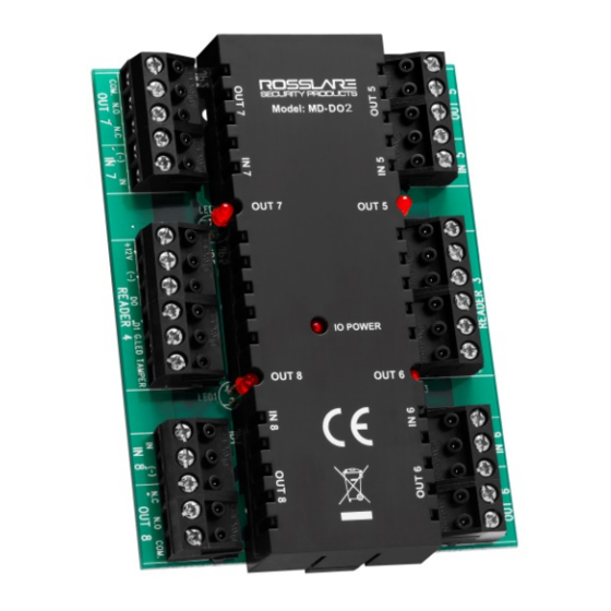
Figure 1: MD-D02 Access Controller Expansion Board
2.3
P hysical Characteristics
7 B
Dimensions (L x W x D)
100 x 75.9 x 32.5 mm (3.94 x 2.99 x 1.28 in.)
Weight
98.2 g (3.46 oz)
2.4
R eader Characteristics
8 B
Reader Output Voltage
12 VDC
Max. Reader Current:
245 mA
LED Control Output
Open collector, Active low
Tamper Input
5 VDC maximum voltage, optical anti-tamper
sensor
Supported Formats
Various (refer to the AxTraxNG™ software manual)
2.5
L ED Indicators
9 B
Power LED
Active when connected to a power source
Output LEDs
Four LEDs
Each output LED is active when an output relay is
energized and N.O. to COM contacts are shorted.
3.1
A ttaching the MD-D02
1 0 B
1. Disconnect power to the access control panel before attaching the
MD-D02.
2. Remove the MD-D02 cover by lightly pulling one of the cover
knobs away from the circuit board. The entire cover comes away
from the board.
3. Peel off the label on the cover of the panel marked "Remove to
install I/O board". The label is located on the same side of the
panel as the DIP switch.
4. Insert the 10-pin male connector of the MD-D02 into the gap in
the panel cover labeled "IO EXPANSION SLOT". The text on the
MD-D02 must face the same way as the text on the panel cover.
5. Tighten the screws securing the cover to the access control panel,
and the four Philips screws on the MD-D02 circuit board.
6. Replace the cover on the expansion board, using it as a guide to
ease the MD-D02 into the panel's 10-pin female connector.
1
Advertisement

Related Manuals for Rosslare MD-D02


Summary of Contents for Rosslare MD-D02
- Page 1 I/O board". The label is located on the same side of the panel as the DIP switch. 4. Insert the 10-pin male connector of the MD-D02 into the gap in the panel cover labeled "IO EXPANSION SLOT". The text on the MD-D02 must face the same way as the text on the panel cover.
- Page 2 4. Wiring Instructions Input Wiring Options Figure 6 shows the normally open supervised input connection with double resistor. There are six input wiring options: Figure 6: Normally Open Supervised Inputs with Double Resistor Normally Open Normally Closed Normally Open ...
- Page 3 5. Using the MD-D02 Operating the MD-D02 The access control panel detects the MD-D02 expansion board when it powers up. When defining the panel in the access control panel's PC application (such as AxTraxNG™), select the option designating the panel name with a designation of “MD-D02”.
- Page 4 Limited Warranty The full ROSSLARE Limited Warranty Statement is available in the Quick Links section on the ROSSLARE website at www.rosslaresecurity.com. Rosslare considers any use of this product as agreement to the Warranty Terms even if you do not review them.
Need help?
Do you have a question about the MD-D02 and is the answer not in the manual?
Questions and answers