Bose Companion 3 Service Manual
Multimedia speaker system
Hide thumbs
Also See for Companion 3:
- Owner's manual (40 pages) ,
- Owner's manual (40 pages) ,
- Owner's manual (26 pages)
Advertisement
Table of Contents
- 1 Table of Contents
- 2 Safety Information
- 3 Electrostatic Discharge Sensitive (ESDS) Device Handling
- 4 Specifications
- 5 Part List Notes
- 6 Bass Module Assembly Parts List
- 7 Amplifier Module Assembly Parts List
- 8 Packing Parts List
- 9 Electrical Parts List
- 10 Main PCB Assembly Parts List
- 11 Power Supply PCB Assembly Parts List
- 12 Disassembly Procedures
- 13 Test Procedures
- 14 Theory of Operation
- 15 Theory of Operation
- 16 Revision History
- Download this manual
®
Companion
3 Multimedia
Speaker System
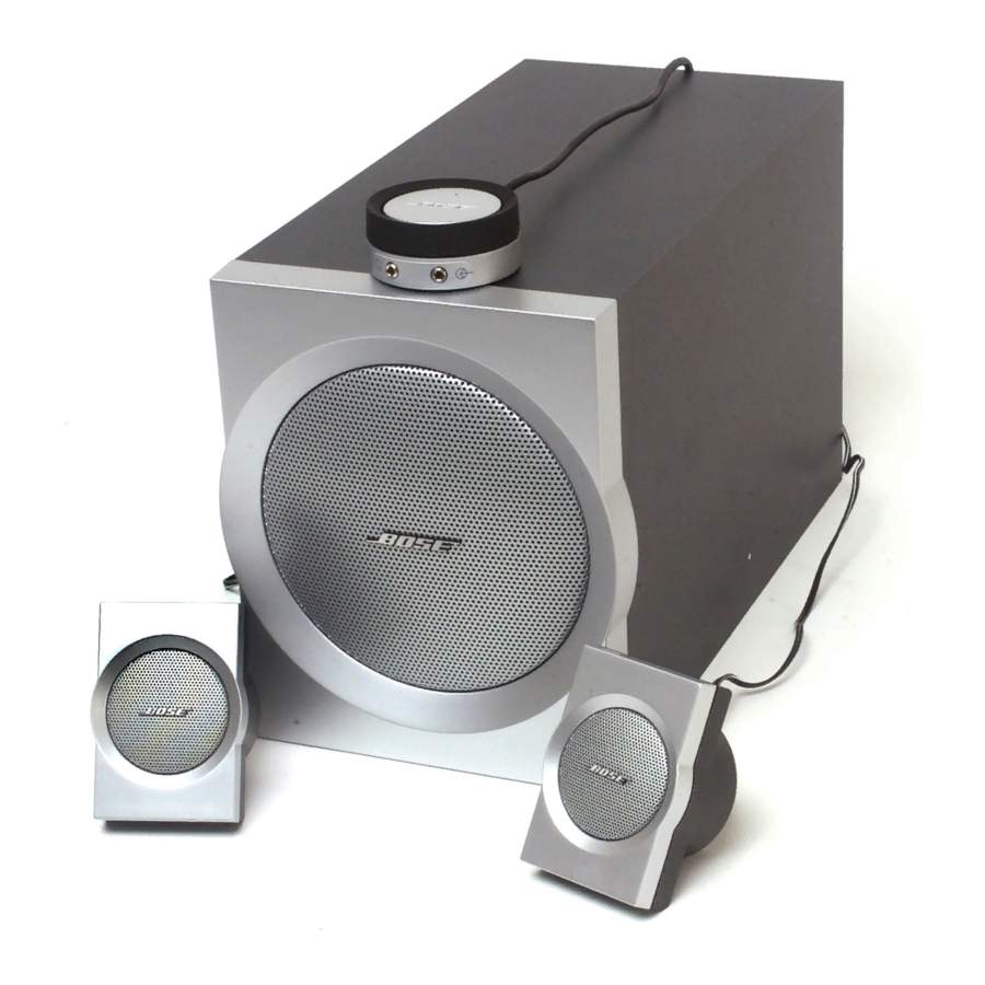
Product Description
The Companion 3 multimedia speaker system is a stereo system designed to be used as a computer sound
system. It can be used with any analog audio source. It has a bass module with a 6.5 inch dual voice coil
woofer in a slot ported design. The two satellite speakers connect to the bass module and are easily mounted
to a monitor with brackets, or can be placed on a desk or other desired surface. A wired remote control pod is
used to control volume and mute/un-mute functions. It also has a second input and a stereo headphone output.
Manufacturing Information - Early Version / Later Version
There are two different versions of the Companion 3 - Early Version / Later Version. From the outside there is
basically no difference but the boards inside are different. Please note the differences are documented in the
Electronic Part list. If a part numbers has changed from the early version or a part number has been added to
the later version a number 4 will be shown in Notes column. The product codes can be used to determined the
version. The product code for the early version is 033935 and the product code for the later version is 033061.
These product codes are the first six digits of the serial number and are located on the bottom of the system.
The serial number should be used to determined where the system was manufactured before attempting a
repair.
Service Manual
©2007 Bose Corporation
Reference Number 271885-SM Rev. 11
Electronic copy only
Advertisement
Table of Contents

Related Manuals for Bose Companion 3


Summary of Contents for Bose Companion 3
- Page 1 Manufacturing Information - Early Version / Later Version There are two different versions of the Companion 3 - Early Version / Later Version. From the outside there is basically no difference but the boards inside are different. Please note the differences are documented in the Electronic Part list.
-
Page 2: Table Of Contents
SERVICE CENTER OR OWNER OF THE BOSE PRODUCT, AND SHALL NOT BE REPRODUCED OR USED FOR ANY OTHER PURPOSE. Caution: The Companion 3 MultiMedia Speaker System contains no user serviceable parts. To prevent warranty infractions, refer servicing to warranty service centers or factory service. -
Page 3: Safety Information
Safety Information 1. Parts that have special safety characteristics are identified by the symbol on the schematics or by special notes on the parts list. Use only replacement parts that have critical characteristics recommended by the manufacturer. 2. Make leakage current or resistance measurements to determine that exposed parts are acceptably insulated from the supply circuit before returning the unit to the customer. -
Page 4: Specifications
Specifications Mechanical Dimensions: Bass Module: 8 5/8 “H x 7 1/8” W x 14” D (21.8 x 18 x 35.56 cm) Satellite Speaker: 3 1/2” H x 2 1/2” W x 2 3/8” D (8.89 x 6.35 x 6.10 cm) Control Pod: 2 1/2 “D x 1 1/8”... -
Page 5: Part List Notes
4. The part number listed was included in the latest version of the Companion 3. The Main board and the Power board for the latest version can be identified by the part number stamped on the compo- nent side of the board. -
Page 6: Bass Module Assembly Parts List
Item Description Part Number Qty. Note BASS MODULE ASSY, US/CANADA, 120V *282451-001 BASS MODULE ASSY, JAPAN, 100V *282451-002 BASS MODULE ASSY, EURO, 230V *282451-003 (Complete package, includes Amp Mod Assy.) CLEAT, ABS 271817-001 SCREW, 4 x 1, THDF, FLHD, 82 DEG, PH 274151-16 CLIP, SPRING, KNOB 262542... -
Page 7: Amplifier Module Assembly Parts List
Figure 2. Amplifier Module Assembly Item Description Part Number Qty. Note PCB ASSY, MAIN 280109-01 BRACKET, METAL, IC 271859 HEATSINK, EXTRUDED, COMP 3 271856 CLIP, THERMAL, THERMISTOR 272964-001 HEAT SPREADER, ALUM 279844-001 SCREW, TAPP, 6-13x.625, PAN, XRC/S 172783-10 CONN, SWITCH, POWER, 3P 273115-001 PCB ASSY, PS, 120V, US 307872-011... -
Page 8: Packing Parts List
10 11 12 13 14 Figure 3. Packaging Exploded View Item Description Part Notes Number Number OWNER’S GUIDE US/CANADA 271883-001 OWNER’S GUIDE 5 LANG 272956 BAG, POLY, 14.38 x 9.87 x 2 mil 103351 PACKING TUBE, 4.75 x 2.75 x 7.69 273522 BASS MODULE ASSY, US/CANADA, 120V 282451-001... -
Page 9: Electrical Parts List
ELECTRICAL PARTS LIST Main PCB Assembly Resistors Reference Description Part Number Note Designator 1.00K, 0805, 1/10W, 1% 133625-1001 1.00K, 0805, 1/10W, 1% 133625-1001 1.00K, 0805, 1/10W, 1% 133625-1001 1.00K, 0805, 1/10W, 1% 133625-1001 2.00K, 0805, 1/10W, 1% 133625-2001 JUMPER, CHIP, 0805 133627 R101 1.21K, 0805, 1/10W, 1%... - Page 10 ELECTRICAL PARTS LIST Main PCB Assembly Resistors (continued) Reference Description Part Number Note Designator R225 100K, 0805, 1/10W, 1% 133625-1003 R226 100K, 0805, 1/10W, 1% 133625-1003 R227 JUMPER, CHIP, 0805 133627 R229 2.55K, 0805, 1/10W, 1% 133625-2551 R230 200K, 0805, 1/10W, 1% 133625-2003 R231 47.5K, 0805, 1/10W, 1%...
- Page 11 ELECTRICAL PARTS LIST Main PCB Assembly Resistors (continued) Reference Description Part Number Note Designator R325 1.21K, 0805, 1/10W, 1% 133625-1212 R327 20.0K, 0805, 1/10W, 1% 133625-2002 R327 JUMPER, CHIP, 0805 133627 R327 JUMPER, CHIP, 0805 133627 Euro R328 JUMPER, CHIP, 0805 133627 R329 16.2K, 0805, 1/10W, 1%...
- Page 12 ELECTRICAL PARTS LIST Main PCB Assembly Resistors (continued) Reference Description Part Number Note Designator R403 221 OHM, 0805, 1/10W, 1% 133625-2210 R404 10.0K, 0805, 1/10W, 1% 133625-1002 R405 1.00K, 0805, 1/10W, 1% 133625-1001 R406 1.00K, 0805, 1/10W, 1% 133625-1001 R407 1.00K, 0805, 1/10W, 1% 133625-1001 R408...
- Page 13 ELECTRICAL PARTS LIST Main PCB Assembly Capacitors Reference Description Part Number Note Designator C001 10000pf, MONO, 100V, 20% 180630-103 C002 10000pf, MONO, 100V, 20% 180630-103 C101 2.2uF, 1206, X7R, 10V, 20% 260361-2253 C102 .0068uF, BOX, 85C, 100V, 5% 137127-682 C103 .033uF, BOX, 85C, 63V, 5% 137127-333 C104...
- Page 14 ELECTRICAL PARTS LIST Main PCB Assembly Capacitors (continued) Reference Description Part Number Note Designator C306 1uF, EL, SMD, 105, 50V, 20% 255071-1R0H C307 1uF, EL, SMD, 105, 50V, 20% 255071-1R0H C308 100pF, 0805, COG, 50V, 5% 133622-101 C309 .015uF, 0805, X7R, 50V, 10% 133623-153 Euro/UK/Aus C310...
- Page 15 ELECTRICAL PARTS LIST Main PCB Assembly Capacitors (continued) Reference Description Part Number Note Designator C336 1000pF, 0805, COG, 50V, 5% 133623-102 Euro/UK/Aus C336 .01uF, 0805, X7R, 50V, 10% 133623-103 C337 10uF, EL, SMD, 105CC, 25V, 20% 255071-100E C338 1000pF, 0805, COG, 50V, 5% 133622-102 C339 1000pF, 0805, COG, 50V, 5%...
- Page 16 ELECTRICAL PARTS LIST Main PCB Assembly Capacitors (continued) Reference Description Part Number Note Designator C966 1000pF, 0805, COG, 50V, 5% 133622-102 C968 .01uF, 0805, X7R, 50V, 10% 133623-103 C969 10uF, EL, SMD, 105C, 25V, 20% 255071-100E C970 1uF, EL, SMD, 105C, 50V, 20% 255071-1R0H C971 .47uF, BOX, 85C, 50V, 5%...
-
Page 17: Power Supply Pcb Assembly Parts List
ELECTRICAL PARTS LIST Main PCB Assembly Transistors Reference Description Part Number Note Designator Q303 BPLR, N, 50V, 800mA, SOT23 148770 Q303 NPN, 1.3W, SOT-223 258416-001 Euro/UK/Aus Q303 NPN, SOT223, 40V, 200mA, 1W 275431 Q304 BPLR, P, 40V, 200mA, SOT23 148596 Q305 BPLR, N, 40V, 200mA, SOT23 146819... - Page 18 ELECTRICAL PARTS LIST Power Supply PCB Assembly Resistors Reference Description Part Number Note Designator 1.00K, 0805, 1/10W, 1% 133625-1001 1.00K, 0805, 1/10W, 1% 133625-1001 1.00K, 0805, 1/10W, 1% 133625-1001 1.00K, 0805, 1/10W, 1% 133625-1001 2.00K, 0805, 1/10W, 1% 133625-2001 10.0 OHM, 0805,1/10W,1% 133625-10R0 10.0 OHM, 0805,1/10W,1% 133625-10R0...
- Page 19 ELECTRICAL PARTS LIST Power Supply PCB Assembly Diodes Reference Description Part Number Note Designator RECTIFIER, BRIDGE, 8A, 400V 260684-400 13V, ZEN, SOD-123, .5W, 5% 174265-5243 SOT-23, BAV 99 147239 Transistors Reference Description Part Number Note Designator BPLR, P, 40V, 200mA, SOT23 148596 BPLR, P, 40V, 200mA, SOT23 148596...
-
Page 20: Disassembly Procedures
Disassembly Procedures 1. Module Assembly Removal 1.1 Remove the knob from the unit. 1.2 Peel back the label and remove it. Note: Use double side tape like 3M double-coated tape number 655 when replacing the label or use a new label. 1.3 Remove the three silver Phillips-head screws located on the right hand side (under the label) and the five Phillips-head or T-15... - Page 21 Disassembly Procedures Speaker Connector 1.5 Disconnect the two connectors shown and remove the module assembly. Transformer Connector Power supply PCB 1.6 Disconnect the two connectors on the power supply PCB. 1.7 Remove the seven T-15 Torx screws shown, to remove the power supply PCB.
- Page 22 Disassembly Procedures 2. Power Transformer Removal 2.1 Remove the module assembly, perform procedure 1. 2.2 Remove the bolt at the center of the power transformer. 2.3 Remove the transformer and shield-can from the bass box. Note: If the new power trans- former has a blue mark on it, align the mark toward the PCB assem- bly for best performance.
-
Page 23: Test Procedures
Test Procedures Test Equipment required: 1. Audio Signal Generator 2. Oscilloscope 3. Digital Multimeter Test Set up Connect the satellites to the output jacks on the bass module. Connect the control pod to the DIN jack on the bass module. Connect a signal generator to the audio input cable and connect the cable to the input jack on the bass module. - Page 24 Test Procedures 3. Bass Module Tone Control Test 3.1 Apply a 90 mVrms, 100 Hz signal to the input of the bass module. 3.2 Set the volume knob on the control pod to maximum (fully clockwise), and set the bass control to it’s center detent (flat) position.
- Page 25 Test Procedures 6. Control Pod Functional Test 6.1 With the system completely set up, turn on the system using the power switch located on the bass module. 6.2 Set the volume knob on the control pod to maximum (fully clockwise), and set the bass control to it’s center detent (flat) position.
-
Page 26: Theory Of Operation
Theory of Operation ® The Companion 3 Multimedia Speaker System is a 2.1 (two channel stereo with one channel subwoofer) system designed to be used as a computer sound system. The Bass Module electronics contain signal processing circuitry and the amplifiers for the woofer and satellites. -
Page 27: Theory Of Operation
Theory of Operation Main Amplifier Board (continued) (refer the schematic diagram 271838) The signals coming into J308 (C7) are sent to sheet 3 of 3 (L_VOL and R_VOL). Three amplifiers in U201 (D8-4) are the equalizers for the right channel and U125, (A8-4) are the equalizers for the left channel. - Page 28 Theory of Operation Main Amplifier Board (continued) (refer the schematic diagram 271838) The two satellite signals, and the bass signal are sent to the power Amp IC, U301 (C3). One channel of the power Amp IC is used for each satellite, and the bass signal uses two channels of the power chip to drive both of the woofer voice coils.
-
Page 29: Revision History
SERVICE MANUAL REVISION HISTORY Date Revision Description of Change Change Driven By Pages Level Affected 10/03 Document released at revision Service Manual Release 5/05 Later version part numbers Change to Main added to Manual Board, Power board and Amplifier board. 5/05 Part number change to F1 on Bill of Material... - Page 30 SPECIFICATIONS AND FEATURES SUBJECT TO CHANGE WITHOUT NOTICE Bose Corporation The Mountain Framingham Massachusetts USA 01701 P/N 271885-SM REV.11 04/2007 (H): http://serviceops.bose.com...
Need help?
Do you have a question about the Companion 3 and is the answer not in the manual?
Questions and answers