Table of Contents
Advertisement
Quick Links
SDL4 Converter
User's manual
Version: 2.00 (August 2019)
Model no.: MASDL4CON-ENG
Translation of the original documentation
All values in this manual are current as of its creation. We reserve the right to change the contents of this manual
without notice. B&R Industrial Automation GmbH is not liable for technical or editorial errors and defects in this
manual. In addition, B&R Industrial Automation GmbH assumes no liability for damages that are directly or indirectly
attributable to the delivery, performance or use of this material. We point out that the software and hardware
designations and brand names of the respective companies used in this document are subject to general trademark,
brand or patent protection.
Advertisement
Table of Contents

Related Manuals for B&R Industries SDL4

Summary of Contents for B&R Industries SDL4
- Page 1 SDL4 Converter User's manual Version: 2.00 (August 2019) Model no.: MASDL4CON-ENG Translation of the original documentation All values in this manual are current as of its creation. We reserve the right to change the contents of this manual without notice. B&R Industrial Automation GmbH is not liable for technical or editorial errors and defects in this manual.
-
Page 2: Table Of Contents
5.4.1 Installing the DC power cable......................... 32 5.4.1.1 Wiring..............................32 5.4.2 Connecting the power supply to a B&R device..................33 5.4.3 Grounding concept - Functional ground....................34 5.5 Connecting cables............................35 SDL4 Converter User's manual V 2.00 Translation of the original documentation... - Page 3 10.3.6.1 5CAUSB.00xx-00..........................61 10.4 Cable strain relief clip..........................63 10.4.1 General information..........................63 10.4.2 Order data............................. 63 10.4.3 Technical data............................63 11 Environmentally friendly disposal...............64 11.1 Separation of materials..........................64 SDL4 Converter User's manual V 2.00 Translation of the original documentation...
-
Page 4: Introduction
Over 6 to 30 mm ±0.2 mm Over 30 to 120 mm ±0.3 mm Over 120 to 400 mm ±0.5 mm Over 400 to 1000 mm ±0.8 mm Table 3: Nominal dimension ranges SDL4 Converter User's manual V 2.00 Translation of the original documentation... -
Page 5: General Safety Guidelines
Electronic devices are generally not failsafe. If the programmable logic controller, operating or control device or uninterruptible power supply fails, the user is responsible for ensuring that connected devices (such as motors) are brought to a safe state. SDL4 Converter User's manual V 2.00 Translation of the original documentation... -
Page 6: Transport And Storage
(e.g. cutout installation). The back of all devices must be protected against the ingress of dust and moisture, however, or the dust deposits must be removed at suitable intervals. SDL4 Converter User's manual V 2.00 Translation of the original documentation... -
Page 7: Programs, Viruses And Malicious Programs
• Import of updates or patches for third-party software (non-B&R software) • Hardware replacement These tests should ensure that implemented security measures remain effective and that systems behave as expected. SDL4 Converter User's manual V 2.00 Translation of the original documentation... -
Page 8: System Overview
System overview 3 System overview 3.1 Information about this user's manual This user's manual contains all necessary information about the SDL4 Converter. For information about SDL4 link modules and SDL4 transmitters, see the Automation Panel and Automation PC user's manuals. Information: All specifications in dimension diagrams and associated tables are in millimeters [mm]. -
Page 9: Connection Options
The brightness of the display can be set via the ADI Control Center. Operation with a USB type A/B cable The Automation Panel can be up to 100 m away from the SDL4 Converter; USB 2.0 is fully integrated in SDL4 and transferred over this distance. - Page 10 Maximum cable length of SDL and USB: 5 m Requirements • Automation Panel with SDL4 receiver • B&R industrial PC with SDL interface • SDL4 Converter • SDL cable, USB type A/B cable, SDL3/SDL4 cable SDL4 Converter User's manual V 2.00 Translation of the original documentation...
- Page 11 System overview Operation without a USB type A/B cable The maximum distance for transferring data between the B&R industrial PC and SDL4 Converter (5COSD4.1000-00, 5COSD4.1001-00) is 10 m; USB 1.1 is fully integrated in the SDL transfer and transferred over this distance.
-
Page 12: Sdl4 Operation With Sdl4 Converter Via Dvi
Automation Panel is connected to the SDL4 Converter using an SDL3/SDL4 cable. The touch screen data from the multi-touch screen is transferred via the USB type A/B cable. The Automation Panel can be up to 100 m away from the SDL4 Converter; USB 2.0 is fully integrated in SDL4 and transferred over this distance. - Page 13 System overview ° Firmware updates are not possible. ° Adjusting the display brightness is not possible. SDL4 Converter User's manual V 2.00 Translation of the original documentation...
-
Page 14: General Limitations/Characteristics
SDL4 currently supports up to eight downstream ports per hub. This means that it is possible to identify all eight ports on a given hub. By comparison, if SDL4 supported only four ports per hub, ports five to eight – on an eight- port hub –... - Page 15 • A maximum of six additional USB devices can be connected. • Maximum permissible USB endpoints: Endpoints Transfer rate of the devices High speed Full speed / Low speed SDL4 Converter User's manual V 2.00 Translation of the original documentation...
-
Page 16: Design/Configuration
Power supply connector 0TB103.9 0TB103.91 Accessories Optional selection Cable strain relief clip 5ACCRHMI.0011-000 Only required for SDL operation. Only required for DVI operation. Optional for SDL operation, required for DVI operation. SDL4 Converter User's manual V 2.00 Translation of the original documentation... -
Page 17: System Data
The SDL4 Converter makes operation via SDL4 with Automation Panels possible for B&R industrial PCs that are not equipped with an SDL4 interface or SDL4 slot. This makes it easy to upgrade systems to SDL4 as part of retrofit measures and conversions. -
Page 18: Technical Data
Top-hat rail clamp set X20AC0RF1 can also be used for improved installation / vibration resistance. Vibration testing is performed per EN 60068-2-6. Shock testing is performed per EN 60068-2-27. SDL4 Converter User's manual V 2.00 Translation of the original documentation... -
Page 19: Dimensions
All specifications in dimension diagrams and associated tables are in millimeters [mm]. 2D and 3D diagrams (DXF and STEP formats) can be downloaded from the B&R website (www.br-automation.com). 5COSD4.1000-00 Figure 1: 5COSD3.1000-00 - Dimensions 5COSD4.1001-00 Figure 2: 5COSD4.1001-00 - Dimensions SDL4 Converter User's manual V 2.00 Translation of the original documentation... -
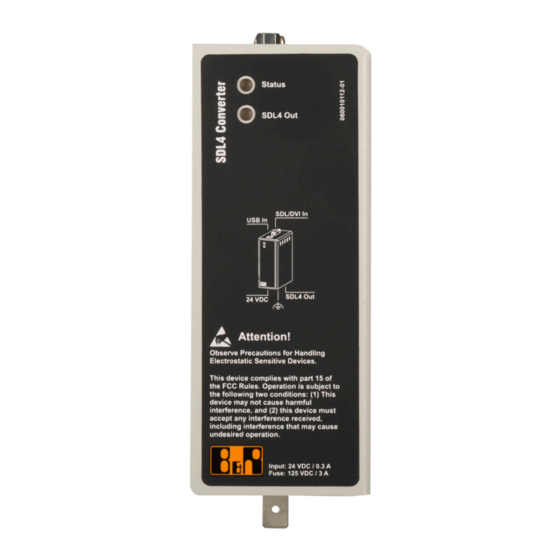
Page 20: Device Interfaces
"USB In interface" on page 23 "+24 VDC power supply" on page 21 "SDL/DVI In interface" on page 22 "Grounding" on page 21 "SDL4 Out interfaces" on page 23 SDL4 Converter User's manual V 2.00 Translation of the original documentation... - Page 21 The wire cross section should be as large as possible (at least 2.5 mm²). SDL4 Converter User's manual V 2.00 Translation of the original documentation...
- Page 22 5CADVI.0018-00 5CADVI.0018-00 5CADVI.0018-00 5CADVI.0018-00 5CADVI.0018-00 5CADVI.0018-00 5CADVI.0018-00 5CADVI.0050-00 5CADVI.0050-00 5CADVI.0050-00 5CADVI.0050-00 5CADVI.0050-00 5CADVI.0050-00 5CADVI.0050-00 The maximum cable length for DVI transfer is limited to 5 m due to the USB specification. SDL4 Converter User's manual V 2.00 Translation of the original documentation...
- Page 23 System overview 3.6.2.1.4 SDL4 Out interfaces The SDL4 Out interfaces are female RJ45 connectors and operated with SDL4 transmission technology. Quantity and description • 5COSD4.1000-00: 1 SDL4 output (SDL4 Out) • 5COSD4.1001-00: 3 SDL4 outputs (SDL4 Out 0-2) Information: Hot plugging output devices on the interface for service purposes is supported by the hardware and graphic drivers of approved operating systems.
- Page 24 No active SDL and SDL4 connection, but link (approx. 1 partner found. Information: In DVI mode, this LED blinks to indi- cate limited SDL4 operation. Blinking Firmware upgrade is in progress. (approx. 10 SDL4 Converter User's manual V 2.00 Translation of the original documentation...
-
Page 25: Overview
Connector 24 VDC - 3-pin female - Screw clamp terminal block 3.31 mm² 0TB103.91 Connector 24 VDC - 3-pin female - Cage clamp terminal block 3.31 mm² 5ACCRHMI.0011-000 REP strain relief USB - For APC2100/APC2200 - For SDL3 Converter/SDL4 Converter Converter 5COSD4.1000-00 SDL to SDL4 1x converter 5COSD4.1001-00... -
Page 26: Dimensioning
If the specified spacing for air circulation cannot be maintained, the maximum specified temperatures of the temperature sensors (see "Temperature sensors" on page 27) must be monitored by the user and appropriate measures taken if these values are exceeded. SDL4 Converter User's manual V 2.00 Translation of the original documentation... -
Page 27: Temperature Monitoring
Dimensioning 4.2 Temperature monitoring Two sensors monitor the temperature values in the SDL4 Converter. The values specified represent the defined maximum temperature at this measuring point. If the temperature is exceeded, no alarm is triggered. ADI sensors Max. specified temperature [°C]... -
Page 28: Installation And Wiring
• This device is only approved for use in closed rooms and not permitted to be exposed to direct sunlight. • The climatic and ambient conditions must be taken into account, see the technical data of the converter used. SDL4 Converter User's manual V 2.00 Translation of the original documentation... - Page 29 Damaged packaging indicates that the device has been severely affected by environmental influences and may have been damaged. This can result in malfunctions of the device, machine or system. SDL4 Converter User's manual V 2.00 Translation of the original documentation...
-
Page 30: Installing The Sdl4 Converter
Figure 6: Top-hat rail 5.2.1 Procedure 1. Attach the SDL4 Converter in the desired position to the top-hat rail (1) and press down (2) on the device to engage the locking mechanism (3). SDL4 Converter User's manual V 2.00 Translation of the original documentation... -
Page 31: Installing The Cable Strain Relief Clip
Installation and wiring 5.3 Installing the cable strain relief clip 1. The cable strain relief clip must be positioned on the SDL4 Converter according to the following figure and secured with the supplied locating screws (M3, max. tightening torque 0.5 Nm). -
Page 32: Connecting To The Power Grid
Insert a screwdriver into the cage clamp terminals ➀ and secure the conductors with wire end sleeves in the terminal contacts ➁ as shown in the figure below. Close the terminal contact by removing the screwdriver. 24 VDC 0 VDC SDL4 Converter User's manual V 2.00 Translation of the original documentation... -
Page 33: Connecting The Power Supply To A B&R Device
2. Connect the power supply connector to the B&R device and tighten the mounting screws (max. tightening torque 0.5 Nm). Figure 8: Connecting the power supply connector to a B&R device SDL4 Converter User's manual V 2.00 Translation of the original documentation... -
Page 34: Grounding Concept - Functional Ground
The functional ground on the B&R device is marked with the following symbol: Legend Power supply connection +24 VDC pin 2 Central grounding point Ground connection At least 1.5 mm² At least 2.5 mm² SDL4 Converter User's manual V 2.00 Translation of the original documentation... -
Page 35: Connecting Cables
B&R generally recommends connecting swing arm devices to the Automation PC via SDL4 instead of SDL. The Cat 6 / Cat 7 cables used with SDL4 are much easier to install and connect. When connecting or installing cables, the bend radius specification must be observed. -
Page 36: Removing The Sdl4 Converter
5.6 Removing the SDL4 Converter 5.6.1 Procedure 1. Pull the SDL4 Converter downwards (1) and slightly in the opposite direction away from the top-hat rail (2). This releases the locking mechanism for the top-hat rail installation. SDL4 Converter User's manual V 2.00 Translation of the original documentation... -
Page 37: Commissioning
• An Automation PC or Panel PC and Automation Panel are connected. 6.1.2 Switching on the SDL4 Converter Procedure 1. Connect the power supply and switch it on. 2. The device is operating. SDL4 Converter User's manual V 2.00 Translation of the original documentation... -
Page 38: Software
To upgrade the firmware, an APC910/PPC900, APC2200 or APC3100/PPC3100 with compatible MTCX firmware must be connected in addition to an Automation Panel with an SDL4 link module. A current firmware upgrade can be downloaded directly from the Downloads section of the B&R website (www.br-... -
Page 39: Maintenance
Repairs are therefore only permitted to be carried out by authorized qualified personnel at the manufacturer's premises. To process a repair/complaint, a repair order or complaint must be created via the B&R Material Return Portal on the B&R website (www.br-automation.com). SDL4 Converter User's manual V 2.00 Translation of the original documentation... -
Page 40: International And National Certifications
Electromagnetic compatibility (EMC) - Part 6-4: Generic standards - Emission stan- dard for industrial environments Information: The declarations of conformity are available on the B&R website under Downloads - Certificates - Declarations of conformity. SDL4 Converter User's manual V 2.00 Translation of the original documentation... -
Page 41: Certifications
Eurasian Customs Union (based on EU conformity). 9.2.3 KC Products with this mark are tested by an accredited test laboratory and permitted to be introduced into the Korean market (based on EU conformity). SDL4 Converter User's manual V 2.00 Translation of the original documentation... -
Page 42: Rcm
Products with this mark are tested by an accredited test laboratory and certified by the ACMA. The mark is valid for Australia/Oceania and facilitates the certification of your machines and systems in this economic area (based on EU conformity). SDL4 Converter User's manual V 2.00 Translation of the original documentation... -
Page 43: Accessories
(see "Cable strain relief clip" on page 10.1.1 Accessories - Order data Material number Description 5ACCRHMI.0000-000 REP HMI grounding clip 5ACCRHMI.0011-000 REP strain relief USB - For APC2100/APC2200 - For SDL3 Converter/SDL4 Converter SDL4 Converter User's manual V 2.00 Translation of the original documentation... -
Page 44: 0Tb103.9X
Yes, but applies only if all components installed in the complete system have this certification and are listed on the associated DNV GL certificate for the product family. The cage clamp terminal block cannot be used side by side. The respective limit data of the I/O modules must be taken into account! SDL4 Converter User's manual V 2.00 Translation of the original documentation... -
Page 45: Cables
10.3.1 SDL3/SDL4 cables 10.3.1.1 5CASD3.xxxx-00 10.3.1.1.1 General information 5CASD3.xxxx-00 SDL3/SDL4 cables are designed to transfer SDL3/SDL4 data and enable easy cable installation. Due to the RJ45 connector, the cable is also suitable for narrow feed-throughs, e.g. in swing arm shafts. Caution! The cable is only permitted to be connected/disconnected when the power is switched off. - Page 46 Yes, but applies only if all components installed in the complete system have this certification and the complete system bears the corresponding mark. At 20°C ambient temperature. 10.3.1.1.4 Bend radius specification Connector Bend radius Figure 10: SDL3/SDL4 - Bend radius specification 10.3.1.1.5 Dimensions Length Figure 11: 5CASD3.xxxx-00 - Dimensions SDL4 Converter User's manual V 2.00 Translation of the original documentation...
- Page 47 Patch cable Patch cable Patch panel Patch panel B&R device B&R device Field-assembled cable Max. 5 m Max. 5 m Max. 100 m Figure 12: Wiring with a field-assembled cable SDL4 Converter User's manual V 2.00 Translation of the original documentation...
-
Page 48: Sdl Cables
28 AWG ≤237 Ω/km Insulation resistance Min. 10 MΩ/km Operating conditions Pollution degree per EN 61131-2 Pollution degree 2 Table 12: 5CASDL.0008-00, 5CASDL.0018-00, 5CASDL.0050-00, 5CASDL.0060-00, 5CASDL.0100-00 - Technical data SDL4 Converter User's manual V 2.00 Translation of the original documentation... - Page 49 Connector - Ferrite bead Ferrite bead - Ferrite bead Ferrite bead Ferrite bead Figure 13: Bend radius specification 10.3.2.1.5 Dimensions 35 ±5 40 ±1 Length Figure 14: 5CASDL.0xxx-00- Dimensions SDL4 Converter User's manual V 2.00 Translation of the original documentation...
- Page 50 XUSB1 negative TMDS data 1 negative XUSB1 positive TMDS data 1 positive TMDS data shield TMDS data 1 and XUSB0 shield TMDS clock positive XUSB0 negative TMDS clock negative SDL4 Converter User's manual V 2.00 Translation of the original documentation...
-
Page 51: Sdl Cables With 45° Connector
Dimensions Length 1.8 m ±30 mm 5 m ±50 mm 10 m ±100 mm Diameter Max. 9 mm Max. 11.5 mm Table 14: 5CASDL.0018-01, 5CASDL.0050-01, 5CASDL.0100-01 - Technical data SDL4 Converter User's manual V 2.00 Translation of the original documentation... - Page 52 Connector - Ferrite bead Ferrite bead - Ferrite bead Ferrite bead Ferrite bead Figure 15: Bend radius specification 10.3.3.1.5 Dimensions 35 ±5 40 ±1 Length Figure 16: 5CASDL.0xxx-01 - Dimensions SDL4 Converter User's manual V 2.00 Translation of the original documentation...
- Page 53 XUSB1 negative TMDS data 1 negative XUSB1 positive TMDS data 1 positive TMDS data shield TMDS data 1 and XUSB0 shield TMDS clock positive XUSB0 negative TMDS clock negative SDL4 Converter User's manual V 2.00 Translation of the original documentation...
-
Page 54: Sdl Flex Cables
0.5 kV Wave impedance 100 ±10 Ω Conductor resistance 24 AWG ≤95 Ω/km 26 AWG ≤145 Ω/km Insulation resistance >200 MΩ/km Table 16: 5CASDL.0018-03, 5CASDL.0050-03, 5CASDL.0100-03 - Technical data SDL4 Converter User's manual V 2.00 Translation of the original documentation... - Page 55 Connector - Ferrite bead Ferrite bead - Ferrite bead Ferrite bead Ferrite bead Figure 17: Bend radius specification 10.3.4.1.5 Dimensions 15.5 110 ±10 Length Figure 18: 5CASDL.0xxx-03 ≥ Rev. E0 - Dimensions SDL4 Converter User's manual V 2.00 Translation of the original documentation...
- Page 56 - +5 V XUSB1 - Ground DDC data 24 AWG - Hot plug detect Control wires +5 V 24 AWG XUSB0 Ground 24 AWG Hot plug detection 24 AWG SDL4 Converter User's manual V 2.00 Translation of the original documentation...
- Page 57 XUSB1 negative TMDS data 1 negative XUSB1 positive TMDS data 1 positive TMDS data shield TMDS data 1 and XUSB0 shield TMDS clock positive XUSB0 negative TMDS clock negative SDL4 Converter User's manual V 2.00 Translation of the original documentation...
-
Page 58: Dvi Cables
Table 18: 5CADVI.0018-00, 5CADVI.0050-00 - Technical data Yes, but applies only if all components installed in the complete system have this certification and are listed on the associated DNV GL certificate for the product family. SDL4 Converter User's manual V 2.00 Translation of the original documentation... - Page 59 Connector - Ferrite bead Ferrite bead - Ferrite bead Ferrite bead Ferrite bead Figure 20: Bend radius specification 10.3.5.1.5 Dimensions 40 ±1 25 ±5 Length Figure 21: 5CADVI.0xxx-00 - Dimensions SDL4 Converter User's manual V 2.00 Translation of the original documentation...
- Page 60 If you wish to assemble a suitable cable yourself, the cable must be wired according to this pinout. Information: Functionality is only guaranteed for the cables available from B&R. DVI-D (24+1), male DVI-D (24+1), male Cable shield Cable shield Figure 22: 5CADVI.0xxx-00 - Pinout SDL4 Converter User's manual V 2.00 Translation of the original documentation...
-
Page 61: Usb Cables
Table 20: 5CAUSB.0018-00, 5CAUSB.0050-00 - Technical data Yes, but applies only if all components installed in the complete system have this certification and are listed on the associated DNV GL certificate for the product family. SDL4 Converter User's manual V 2.00 Translation of the original documentation... - Page 62 If you wish to assemble a suitable cable yourself, the cable must be wired according to this pinout. Information: Functionality is only guaranteed for the cables available from B&R. USB type A, male USB type B, male Jacket Jacket Figure 23: 5CAUSB.00xx-00 USB cables - Pinout SDL4 Converter User's manual V 2.00 Translation of the original documentation...
-
Page 63: Cable Strain Relief Clip
10.4 Cable strain relief clip 10.4.1 General information A cable strain relief clip is available for the SDL4 Converter. The locating screws and cable ties required for installation on the device are included in delivery. For details about installation, see "Installing the cable strain relief clip"... -
Page 64: Environmentally Friendly Disposal
Operating and monitoring devices Uninterruptible power supplies Batteries and rechargeable batteries Cables Paper/Cardboard packaging Paper/Cardboard recycling Plastic packaging material Plastic recycling Disposal must be carried out in accordance with applicable legal regulations. SDL4 Converter User's manual V 2.00 Translation of the original documentation... - Page 65 Publishing information SDL4 Converter User's manual V 2.00 Translation of the original documentation...
- Page 66 Publishing information Publishing information B&R Industrial Automation GmbH B&R Strasse 1 5142 Eggelsberg Austria Telephone: +43 7748 6586-0 Fax: +43 7748 6586-26 office@br-automation.com SDL4 Converter User's manual V 2.00 Translation of the original documentation...
Need help?
Do you have a question about the SDL4 and is the answer not in the manual?
Questions and answers