Table of Contents
Advertisement
Quick Links
Chipsmall Limited consists of a professional team with an average of over 10 year of expertise in the distribution
of electronic components. Based in Hongkong, we have already established firm and mutual-benefit business
relationships with customers from,Europe,America and south Asia,supplying obsolete and hard-to-find components
to meet their specific needs.
With the principle of "Quality Parts,Customers Priority,Honest Operation,and Considerate Service",our business
mainly focus on the distribution of electronic components. Line cards we deal with include
Microchip,ALPS,ROHM,Xilinx,Pulse,ON,Everlight and Freescale. Main products comprise
IC,Modules,Potentiometer,IC Socket,Relay,Connector.Our parts cover such applications as commercial,industrial,
and automotives areas.
We are looking forward to setting up business relationship with you and hope to provide you with the best service
and solution. Let us make a better world for our industry!
Contact us
Tel: +86-755-8981 8866 Fax: +86-755-8427 6832
Email & Skype: info@chipsmall.com Web: www.chipsmall.com
Address: A1208, Overseas Decoration Building, #122 Zhenhua RD., Futian, Shenzhen, China
Advertisement
Table of Contents

Related Manuals for Industrial Fiber Optics IF


Summary of Contents for Industrial Fiber Optics IF
- Page 1 Chipsmall Limited consists of a professional team with an average of over 10 year of expertise in the distribution of electronic components. Based in Hongkong, we have already established firm and mutual-benefit business relationships with customers from,Europe,America and south Asia,supplying obsolete and hard-to-find components to meet their specific needs.
- Page 2 Digital Photometer Operator’s Manual Model Numbers: IF PM ndustrIal Iber ptIcs...
- Page 3 All rights reserved. No part of this publication may be reproduced, stored in a retrieval system, or transmitted in any form or by any means (electronic, mechanical, photocopying, recording, or otherwise) without prior written permission from Industrial Fiber Optics. * * * * *...
-
Page 4: Introduction
This manual provides information about Industrial Fiber Optics’ Digital Photometer. It contains all the information you need to operate this device safely and knowledgeably, even if you are a novice to this technology. Please read the manual carefully before operating. - Page 5 – ii –...
-
Page 6: Table Of Contents
TABLE OF CONTENTS Introduction………………………....……..…………..…… Laser cLassIFIcatIONs............BackgrOuND................geNeraL INFOrMatION..…......……...……..Control/Display Unit..............PrODuct sPecIFIcatIONs…………....…....... saFety…................………. Electrical..................Optical..................INItIaL checkOut…..............… OPeratINg PrOceDures…............Monitoring Solar Energy.............. Measuring a Laser Beam’s Power..........trOuBLeshOOtINg…............………. servIce aND MaINteNaNce..…......……..…... Battery Installation............... 10 “Zeroing” Procedure..............Malfunctions................. WarraNty..................shIPMeNt DaMage cLaIMs............–... -
Page 7: Laser Classifications
Laser cLassIFIcatIONs All manufacturers of lasers used in the United States must conform to regulations admin- istered by the Center for Devices and Radiological Health (CDRH), a branch of the U.S. Department of Health and Human Services. CDRH categorizes lasers as follows: Class Description A laser or laser system, which does not present a hazard to skin... -
Page 8: Background
BackgrOuND The word “photometer” originates from two other words — photo, which means light, and meter, which means instrument. Together the two words mean “an instrument for measuring light.” Photometers (or light meters) are used in many household and commercial applications, including some we may not be aware of. -
Page 9: General Information
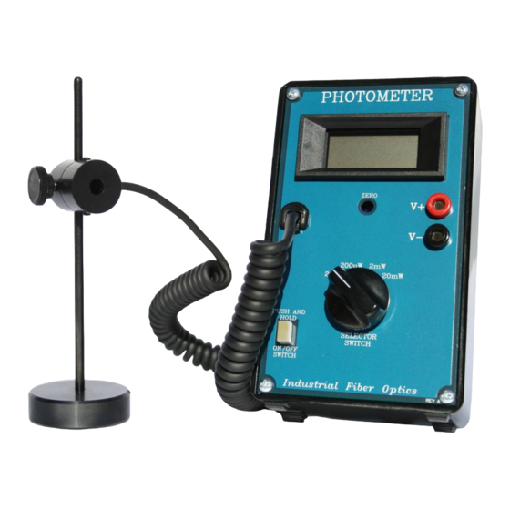
Display (LcD) SELECTOR SWITCH ON/OFF SWITCH The indicator for the Digital Industrial Fiber Optics Photometer is a liquid crystal 1339 display (LCD) with 3-1/2-digit Figure 1. Photometer face. resolution. The maximum display reading is 1999 and the minimum is 0. (When the meter displays a negative number, go to the section entitled “Zeroing”... - Page 10 Assembly is electrically and mechanically connected to the Control/Display Unit by the Cable. It is not meant to be removed from the cable, and your product warranty will be voided if it is removed. Detector The Detector, or light sensing element, is approximately one centimeter square with a 7 mm diameter aperture in the center of the Detector Housing.
- Page 11 11. Batteries (Not shown) The Digital Photometer requires two 9-volt batteries (included) for operation. For shipping and storage purposes they have not been installed at the factory. To install or replace the batteries, follow the procedure in the section entitled SERVICE AND MAINTENANCE.
-
Page 12: Product Specifications
PrODuct sPecIFIcatIONs Table 3. Digital Photometer specifications. Parameter Value Operating Input power 2 9-V batteries Accuracy* ± 10% Range (4) 19.99 µW, 199.9 µW, 1.999 mW, 19.99 mW Temperature 10 to 30° C Optical Detector active area 38 mm Aperture 7 mm Wavelength sensitivity 450 to 1050 nm... -
Page 13: Safety
If you are uncertain or unfamiliar with them, review their operating manuals or contact your instructor or safety officer. -
Page 14: Initial Checkout
Numbers on the LCD display should now be visible. Hold the ON/OFF switch in for 15 seconds. If the LCD does not read zero (± .002 mW) , refer to the section entitled SERVICE AND MAINTENANCE for the procedure to “zero”... -
Page 15: Operating Procedures
Set the Selector Switch to the 20 mW position. Check that the meter reads zero (± .002 mW) when the detector is covered and the On/Off Switch is closed. If not, go to the section titled “Zeroing” Procedure under Service and Maintenance. -
Page 16: Troubleshooting
Detector Photometer beyond Assembly. Reposition Detector Assembly or light the steps listed above. source. If you believe that a • Selector Switch is set at too high a level. Turn problem exists within Selector Switch counter-clockwise one step. -
Page 17: Service And Maintenance
The only service and maintenance that the Digital Photometer should require is battery replacement and “zeroing.” Instructions for both procedures follow. All other adjustments have been made at Industrial Fiber Optics facilities. Battery Installation The recommended batteries for this meter are standard, heavy-duty or alkaline 9-volt batteries. -
Page 18: Zeroing" Procedure
“Zeroing” Procedure Periodically it may become necessary to adjust the Control/Display Unit so it reads zero. in the absence of light. (When the meter is on the 20 µwatt scale the display sometimes cannot be totally zeroed because of stray ambient light. In those cases, subtract the DC offset from your readings.) Zeroing the Photometer can be done using the following procedure. -
Page 19: Warranty
The costs of return shipments for a Digital Photometer no longer under warranty must be paid by the customer. If an item is not under warranty, repairs will not be undertaken until the cost of such repairs have been prepaid by the customer. Typical repair costs range from $50 - $75, and completion times from two to three weeks. -
Page 20: Shipment Damage Claims
DaMage cLaIMs If damage to an Industrial Fiber Optics product should occur during shipping, it is impera- tive that it be reported immediately, both to the carrier and the distributor or salesperson from whom the item was purchased. DO NOT CONTACT INDUSTRIAL FIBER OPTICS. - Page 21 12 0105 Rules for Laser Safety • Lasers produce a very intense beam of light. Treat them with respect. Most educational lasers have an output of less than 3 milliwatts, and will not harm the skin. • Never look into the laser aperture while the laser is turned on! PERMANENT EYE DAMAGE COULD RESULT.
Need help?
Do you have a question about the IF and is the answer not in the manual?
Questions and answers