Advertisement
Quick Links
LabSat 2 User Manual
•
01 - LabSat 2 Introduction
•
02 - LabSat 2 Operation
•
03 - LabSat 2 Hardware overview
•
04 - LabSat 2 PC Requirements
•
05 - LabSat 2 Installing Software
•
06 - LabSat 2 Connecting USB
•
07 - LabSat 2 Software Overview
•
08 - LabSat 2 Software Settings
•
09 - LabSat 2 Recording GNSS Data
•
10 - LabSat 2 Recording Event Inputs
•
11 - LabSat 2 Replaying GNSS Data
•
12 - LabSat 2 SatGen v2 Software
•
13 - Converting LabSat scenarios
•
14 - LabSat 2 Interface Modules
•
15 - LabSat 2 Video Syncronisation
•
16 - LabSat 2 Advanced functions
•
LabSat 2 - Troubleshooting
•
LabSat 2 - Updating the Firmware
•
17 - LabSat 2 Software Development Kit (SDK)
•
18 - LabSat 2 Inventory and optional extras
•
19 - LabSat 2 PIN OUTS
•
20 - LabSat 2 Technical specifications
1
Advertisement

Summary of Contents for Racelogic LabSat 2
- Page 1 16 - LabSat 2 Advanced functions • LabSat 2 - Troubleshooting • LabSat 2 - Updating the Firmware • 17 - LabSat 2 Software Development Kit (SDK) • 18 - LabSat 2 Inventory and optional extras • 19 - LabSat 2 PIN OUTS •...
- Page 2 (Channels 06 to -7 or approximately 1606 MHz down to 1598 MHz) signal and has no limit to the number of satellites that can be logged. In addition to recorded data, the Labsat 2 can replay simulated, GPS L1 and or GLONASS L1 scenarios generated using the optional Racelogic SatGen v2 software.
- Page 3 • Reacquisition Time https://en.racelogic.support//Product_Info/LabSat_2/LabSat_2_User_Guide/01_-_LabSat_2_Introduction...
- Page 4 02 - LabSat 2 Operation Depending on model type, the LabSat 2 is able to record RF data directly from an active antenna and store the data on a hard drive or generate GNSS RF signals from data stored on a hard drive.
- Page 5 The RF OUT port is used to connect the LabSat 2 to the GNSS system under test. The output signal of the LabSat 2 is at a nominal level of -83 dB when replaying previously recorded data. Using the PC software, it is possible to attenuate the LabSat 2 output by approximately 24 dB giving a signal power range of -83 dBm down to -107 dBm.
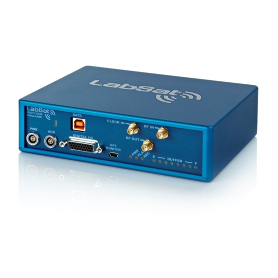
- Page 6 03 - LabSat 2 Hardware overview https://en.racelogic.support//Product_Info/LabSat_2/LabSat_2_User_Guide/03_-_LabSat_2_Hardware_overview...
- Page 7 LEDs Description Comment Power status Green LED indicates power good Indicates that LabSat 2 is in Replay PLAY Replay Indication Mode Indicates that LabSat 2 is in Record Record Indication Mode Indicates buffer status. If status...
- Page 8 04 - LabSat 2 PC Requirements The LabSat 2 uses a USB 2.0 HI-SPEED interface for data transfer. When recording RF signals, the sustained USB transfer rate is in excess of 8Mbytes/s. It is therefore important to ensure that all intensive background tasks such as anti-virus scans are switched off to avoid interruption of data transfer to and from the hard drive.
- Page 9 USB connection from LabSat 2 to the computer. When you connect to the LabSat 2 via USB for the first time you will be required to install USB drivers, please see the section ‘Connecting LabSat 2 USB’ below.
- Page 10 06 - LabSat 2 Connecting USB • Connect the USB A to B cable between the LabSat 2 and the computer. If you intend to use the GNSS monitor connect the Mini USB as well. • The computer should now recognise the presence of a new USB device; after a short period of time a ‘Found New Hardware Wizard’...
- Page 11 https://en.racelogic.support//Product_Info/LabSat_2/LabSat_2_User_Guide/06_-_LabSat_2_Connecting_USB...
- Page 12 07 - LabSat 2 Software Overview The LabSat software is used to control record or replay functions of the LabSat. The picture below shows the LabSat Replay screen. https://en.racelogic.support//Product_Info/LabSat_2/LabSat_2_User_Guide/07_-_LabSat_2_Software_Overview...
- Page 13 The picture below shows the LabSat Record screen. https://en.racelogic.support//Product_Info/LabSat_2/LabSat_2_User_Guide/07_-_LabSat_2_Software_Overview...
- Page 14 08 - LabSat 2 Software Settings The LabSat software can be used to control the multi-GNSS LabSat 2, as well as LabSat hardware. When a LabSat is connected to the PC the LabSat software will auto-detect the type of hardware connected and configure LabSat accordingly.
- Page 15 Hardware Settings: LabSat 2 is a Multi GNSS Replay and Record Simulator. Each Channel is selectable to record and replay from the GPS L1, Galileo E1, BDS B1 or GLONASS L1 RF signals. The system can be set to record a single constellation at 2 bit or in pairs at 1 bit and one constellation with the second channel set to record DIO.
- Page 16 The GNSS Monitor is set to Internal LabSat 2. This uses the internal GPS engine to monitor GPS signals during Replay or Record, on the LabSat software GUI. The monitor can be set to Internal LabSat 2 (10 Hz) which will use up to to eight satellites only in this mode.
- Page 17 https://en.racelogic.support//Product_Info/LabSat_2/LabSat_2_User_Guide/08_-_LabSat_2_Software_Settings...
- Page 18 NB: Applicable to RLLSC02-GNL1 and RLLSR02-GNL1 LabSat 2 Models Only The GNSS antenna supplied with the LabSat 2 is a 3 V active antenna with 28 dB gain. For the best possible signal quality, it is important to maintain a good RF connection between the antenna and the LabSat. Before fixing the antenna to the LabSat, ensure that there are no dust particles in either connector.
- Page 19 The LabSat 2 is set up according to the diagram below. 1. Connect the Active GNSS antenna to the RF IN port of the LabSat 2. 2. Connect the high speed USB cable to the computer on which the Scenario data file is to be recorded. It is possible to connect an external USB drive to the computer and stream the recorded file directly onto this drive.
- Page 20 6. Click the Browse Button. The user will be prompted to enter the filename and choose the location of the recorded file. 7. Click the Record Button. The REC Light on the front panel of LabSat 2 will start to flash, indicating that LabSat 2 is recording GNSS RF data.
- Page 21 The LED display on the LabSat 2 front panel also indicates the status of the buffer. 10. The Advanced Recording Control allows users to pre-select either a fixed recording time or a fixed recording file size.
- Page 22 12. GNSS Monitor displays the NMEA Output from the internal GPS Receiver within LabSat 2. Connect the GNSS Monitor Port (USB Mini ‘B’) to a spare USB Port on your PC. The GPS data being recorded is simultaneously displayed by LabSat 2’s internal GPS receiver engine, on the GNSS Monitor display, as shown below.
- Page 23 Note: LabSat 2 Data Rate LabSat 2 records RF data over high speed USB at a data rate in excess of 8 MB/sec, this means the data files created by LabSat 2 become large very quickly. It is important to ensure that there is sufficient space on the computer or USB hard drive where the recorded data file is to be stored.
- Page 24 10 - LabSat 2 Recording Event Inputs The AUX connection on the front panel of the LabSat 2 carries a digital input which can be used to mark an event such as a brake trigger event. Contact Racelogic for details of hand-held or pedal mounted switches that can be used with LabSat 2 to record events.
- Page 25 5. Start the LabSat software. 6. The LabSat 2 is now ready to replay GNSS data to the DUT (Device under Test). Select the Replay Mode tab on the LabSat 2. The LabSat 2 is now ready to replay GNSS RF data.
- Page 26 The Info button will display a full description of the scenario as entered in the description box display on the record screen. Information is also displayed about the LabSat recorder used and its configuration settings. https://en.racelogic.support//Product_Info/LabSat_2/LabSat_2_User_Guide/11_-_LabSat_2_Replaying_GNSS_Data...
- Page 27 13. The Advanced Playback Control feature on LabSat 2 contains a feature that allows you to repeat the same scenario over again, so that at the end of the scenario replay the LabSat 2 will loop back to the start of the scenario, and start replaying the scenario over again.
- Page 28 It is recommended to try the 0 dB slider setting (-83 dBm output) first. If the GNSS engine under test does not lock onto the LabSat 2 signal at 0 dB then increase the attenuation slider by 0.5 dB at a time and replay the file. It is also advisable to cold start the GPS / GLONASS device under test after starting each replay to clear any almanac data that the GNSS engine may have stored.
- Page 29 17. The digital noise function allows degradation of the replayed GNSS signals by mixing a noise source with the original recorded/simulated file. The Digital Noise slider in the LabSat software is used to adjust the output signal from 0% noise to 100% noise. At the 0% noise setting, the signal output is 100% of the original signal. https://en.racelogic.support//Product_Info/LabSat_2/LabSat_2_User_Guide/11_-_LabSat_2_Replaying_GNSS_Data...
- Page 30 The LabSat scenario file will then play in synchronisation with the Video VBOX video. Please ensure that the GPS monitor is enabled and is showing the live data from the LabSat scenario. https://en.racelogic.support//Product_Info/LabSat_2/LabSat_2_User_Guide/11_-_LabSat_2_Replaying_GNSS_Data...
- Page 31 The video VBOX video shown in the software can be expanded by clicking on it to the full screen size of the computer screen. 20. Click Stop, to halt replay of GNSS RF data and the video replay. https://en.racelogic.support//Product_Info/LabSat_2/LabSat_2_User_Guide/11_-_LabSat_2_Replaying_GNSS_Data...
- Page 32 12 - LabSat 2 SatGen v2 Software SatGen v2 software is a powerful tool for defining and creating RF playback scenario files for use with the LabSat Simulator. For many applications LabSat can record and playback real world, live sky data, but there may be times when you need a more controlled, user definable signal.
- Page 33 Choice of two software programmes: • SatGen v2 GPS Only Simulation Software with ‘LabSat’ 1 bit and ‘LabSat 2’ 2 bit GPS RF data output in static or dynamic modes: User configurable time, date and duration for static scenario creation. SatGen v2 dynamic scenario creation with draw a route, file upload and user defined command options.
- Page 34 LabSat uses a binary Intermediate Frequency, to down convert GPS RF data into a binary file, whereas LabSat 2 stores GNSS RF data as an IQ binary file. This means that existing LabSat scenarios cannot be run natively on a LabSat 2 or vice versa.
- Page 35 Scenario, on the LabSat Scenario Converter. The new LabSat 2 scenario created can now be run on a LabSat 2 GNSS simulator. This new scenario contains only GPS L1 RF and or Galileo E1 data. The RF data for other Constellations is not created by the LabSat Scenario Conversion tool as LabSat does not record those constellations data.
- Page 36 14 - LabSat 2 Interface Modules During recording, the LabSat monitors the digital input pin, precisely recording the event time of LOW to HIGH or HIGH to LOW transitions. The event times are synchronised to the recorded GPS data with a resolution of around 60nS.
- Page 37 For this reason, we do not recommend that the LabSat is used to replay CAN data onto a vehicle or any other CAN Bus in a safety critical application. Note: It is not possible to use a separate digital input when using one of the interface modules. https://en.racelogic.support//Product_Info/LabSat_2/LabSat_2_User_Guide/14_-_LabSat_2_Interface_Modules...
- Page 38 A unique feature of LabSat is the ability to synchronise RF data recording with video from the optional Racelogic Video VBOX GPS data logger. To record video, the Racelogic Video VBOX is simply placed in the test vehicle at the same time as LabSat.
- Page 39 The Video VBOX should be set to ‘Log all of the time’ by pressing the front panel button after it has booted. Please refer to the Video VBOX manual, for full details on how to set up your Racelogic Video VBOX. To record GPS data on the LabSat, please refer to the earlier section: Recording GPS Data with LabSat.
- Page 40 Video Synchronisation folder. To start playing back video, synchronised with the LabSat 2 GPS RF playback, connect the PC’s USB port to the LabSat using the mini USB cable to the GPS monitor on the LabSat 2.
- Page 41 https://en.racelogic.support//Product_Info/LabSat_2/LabSat_2_User_Guide/15_-_LabSat_2_Video_Syncronisation...
-
Page 42: Pause Control
To allow for synchronised record or replay by LabSat 2 the pause input pin is normally pulled high to 3.3 V. When this pin is driven to 0 V the LabSat 2 will pause the record or replay start until 3.3 V is restored. The pause function can be used to start record or relay in synchronisation with other devices. - Page 43 https://en.racelogic.support//Product_Info/LabSat_2/LabSat_2_User_Guide/16_-_LabSat_2_Advanced_functions...
- Page 44 LabSat 2 - Troubleshooting USB Installation failure Due to the nature of USB communications, the installation of the USB drivers may occasionally fail at various stages. Should this happen the procedure should be repeated three or four times if necessary, prior to requesting technical support.
- Page 45 COM port, preventing the LabSat from using it. Optimising USB Connection Speed • LabSat 2 uses a high speed USB 2.0 connection to stream digitised GNSS data from LabSat 2 to the PC during replay and record •...
- Page 46 LabSat 2. 1. Start LabSat 2 with only the GPS monitor Mini USB and power cables connected. 2. Confirm that the current firmware installed in the LabSat 2 is older than the new firmware supplied by clicking on the ‘About’ button.
- Page 47 8. Confirm that the Upgrader has completed the upgrade. 9. Power off and on the LabSat 2 – Confirm your firmware is now upgraded by clicking on the About Button. https://en.racelogic.support//Product_Info/LabSat_2/LabSat_2_Updates/LabSat_2_-_Updating_the_Firmware...
- Page 48 17 - LabSat 2 Software Development Kit (SDK) All LabSat functionality available through the graphical user interface is also made available by way of an API for customers to integrate into their own production testing or laboratory environment. The LabSat API is provided as a managed C# assembly requiring the Microsoft .Net 4.0 Client Profile runtime. As well as being accessible from managed .Net code, the API is made COM visible allowing a wide range of programming...
- Page 49 18 - LabSat 2 Inventory and optional extras Standard equipment (RLLSx02-GNL1) Description Part Number LabSat 2 Main Unit LS02 LabSat Scenario Hard Disk Drive 500GB USB Drive LS02HDD Mains Power Supply RLVBACS020 USB ‘A’ to USB ‘B’ Lead - 2M RLCAB042 USB ‘A’...
-
Page 50: Optional Equipment
Dual CAN Bus Interface Module RLLSIM04 SatGen v2 Software - GPS only scenario creation software. (Please contact your LabSat distributor or RLLSSGSW02 Racelogic for details) SatGen Software – GPS / GLONASS scenario creation software. (Please contact your LabSat distributor or RLLSSGSWG Racelogic for details) - Page 51 19 - LabSat 2 PIN OUTS Front View of LabSat 2 https://en.racelogic.support//Product_Info/LabSat_2/LabSat_2_User_Guide/19_-_LabSat_2_PIN_OUTS...
- Page 52 Connector 1 - POWER (Lemo 2 PIN) Function Range Power+ 5.4 V to 30 V Ground https://en.racelogic.support//Product_Info/LabSat_2/LabSat_2_User_Guide/19_-_LabSat_2_PIN_OUTS...
- Page 53 Connector 2 - AUX (Lemo 5 PIN) Function Range Module Direction Control ±12 V Reserved ±12 V Digital Input 1 (DIG IN) 0 V to 5 V Digital Output 1 0 V to 5 V +V Power Same as Power+ https://en.racelogic.support//Product_Info/LabSat_2/LabSat_2_User_Guide/19_-_LabSat_2_PIN_OUTS...
- Page 54 Range RF Signal including RF IN 3 V DC bias for active antenna Center RF Signal Output DC RF OUT Blocked 10 MHz Reference CLOCK IN clock. Must be enabled in 10.000 MHz +6 dB LabSat software Chassis Ground https://en.racelogic.support//Product_Info/LabSat_2/LabSat_2_User_Guide/19_-_LabSat_2_PIN_OUTS...
- Page 55 26 way D type connector The functionality available from the 26 Way D-Type connector on the front panel of LabSat 2, is described in the table below. Number Name Function 1-PPS (From Internal DIO 0 GPS when locked to rec/...
- Page 56 DIO 10 output. 0=Inactive / 1=Recording Active Trigger Output (Recorded Trigger Output during DIO 11 replay or pass-through of Trig In during record) Connect to pin 14(GND) Update to Enable firmware update mode on power-on Not used Not used https://en.racelogic.support//Product_Info/LabSat_2/LabSat_2_User_Guide/19_-_LabSat_2_PIN_OUTS...
- Page 57 Function Connected to PWR input V_PWR (max 200 mA) Caution! The Digital I/O connector uses 3.3 Volt logic levels. Connection of any of the IO signals to levels above 3.3 Volts will cause permanent damage to the internal logic. https://en.racelogic.support//Product_Info/LabSat_2/LabSat_2_User_Guide/19_-_LabSat_2_PIN_OUTS...
- Page 58 20 - LabSat 2 Technical specifications Interface to PC USB 2.0 Hi-speed 480 Mbit/s PC Requirements Minimum Core i5 with XP/Vista/Win7/Win 8 STD Reference Oscillator 16.368 MHz Temperature controlled +/-2.5 ppm options RF Record Input Connector Single SMA RF Channels RF Channel 1 Centre Frequency Approx 1561.098 MHz or 1575.42 MHz or 1602.00 MHz...
- Page 59 Approx 62 ns 1 PPS Output Yes – When Internal GPS Locked to Input / Output External Reference Clock Input 10 MHz Options OCXO Frequency Stability <+/-1x10-9 Record Only Record GPS, Galileo, GLONASS, BDS Replay Only Record GPS, Galileo, GLONASS, BDS https://en.racelogic.support//Product_Info/LabSat_2/LabSat_2_User_Guide/20_-_LabSat_2_Technical_specifications...
- Page 60 Approx 170 mm x 128 mm x 46 mm Future Options Dual Input / Output RF ports For dual antenna operation GPS L1 P / L2 P GPS Dual frequency operation Stand alone Integrated hard drive and screen Ethernet connectivity Device management over a network https://en.racelogic.support//Product_Info/LabSat_2/LabSat_2_User_Guide/20_-_LabSat_2_Technical_specifications...
-
Page 61: Module Dimensions
Module Dimensions https://en.racelogic.support//Product_Info/LabSat_2/LabSat_2_User_Guide/20_-_LabSat_2_Technical_specifications... - Page 62 https://en.racelogic.support//Product_Info/LabSat_2/LabSat_2_User_Guide/20_-_LabSat_2_Technical_specifications...
Need help?
Do you have a question about the LabSat 2 and is the answer not in the manual?
Questions and answers