Table of Contents
Advertisement
Quick Links
Advertisement
Table of Contents

Subscribe to Our Youtube Channel
Summary of Contents for Bard WGSCRVS-3C
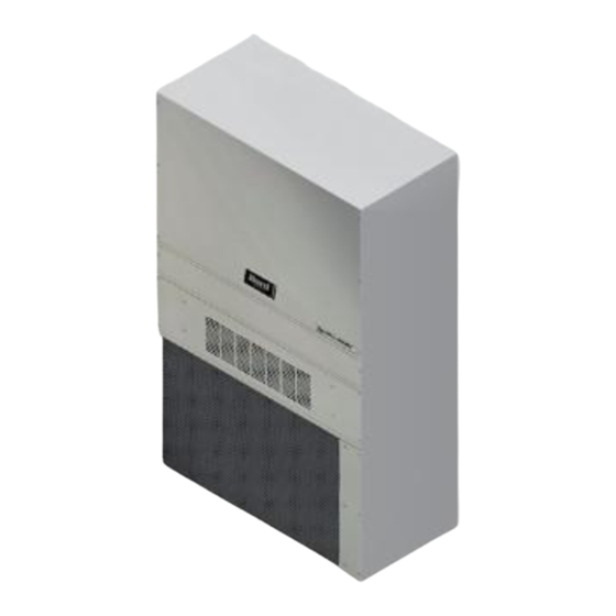
- Page 1 INSTALLATION INSTRUCTIONS Commercial Room Ventilator with Exhaust and CO Modulation (Optional) Models: WGSCRVS-3C WGSCRVS-5C For Use with Bard Single Stage W**G4 Units Bard Manufacturing Company, Inc. Manual : 2100-757 Bryan, Ohio 43506 Supersedes: Date: 12-7-21 www.bardhvac.com Page 1 of 17...
-
Page 2: Table Of Contents
CONTENTS Figures General Information Commercial Room Ventilator Model Nomenclature ... 3 Figure 1 Call for Blower Operation w/o Ventilation ..4 General Information ..........3 Figure 2 Call for Ventilation ........ 5 Unpacking ............3 Figure 3 Removal of Vent Option Panel ....6 Description ............ -
Page 3: General Information
15 days of its receipt. Description The ventilators are designed to be used with Bard 2 − 5 ton single stage wall mount gas electric units. They are electromechanical vent systems designed to provide fresh air to meet indoor air quality standards with built in exhaust provisions. - Page 4 FIGURE 1 Call for Blower Operation without Ventilation Manual 2100-757 Page 4 of 17...
-
Page 5: Figure 2 Call For Ventilation
FIGURE 2 Call for Ventilation Manual 2100-757 Page 5 of 17... -
Page 6: Installation
INSTALLATION 2. Open the front door. Remove and save vent option Basic Installation panel from wall mount unit (see Figure 3). 1. Unpack the ventilator assembly which includes the 3. Remove and save existing unit air filter and screw integral ventilator with attached electrical harness from front center grille (see Figure 5 on page 8 for and miscellaneous hardware. -
Page 7: Figure 4 Loose Piece Wire Harness Plug Install
FIGURE 4 Loose Piece Wire Harness Plug Install 7/8" BUSHING INTO CONTROL PANEL ROUTE WIRES THROUGH WIRE MOUNT, AND INTO HOLE AT REAR OF UNIT INTO LOW VOLTAGE TERMINAL BLOCK AREA PLUG TO SECURE INTO FILTER TRAY MIS-2415 A MIS-2415 7. -
Page 8: Figure 5 Ventilator Installed In Unit
FIGURE 5 Ventilator Installed in Unit Install pin plug in filter partition and wire per diagram Mist Eliminator Plug mating plug from WGCRV into plug in filter partition When installing WGCRV, position so that hole in front lip is centered over hole in condenser grill to insert a self-drilling screw. -
Page 9: Ventilator Checkout
• Method 1: The control board will accept a 2-10VDC signal with a resistive load greater than 5000 ohms. Bard CO sensor part #8403-096 can be used when the 2-10V output is connected to Manual... -
Page 10: Figure 6 Crv Control Board
FIGURE 6 CRV Control Board POT "PP" PRE-PURGE SET FOR PREOCCUPANCY POT "OCC" OCCUPIED SETTING TURN OFF FOR C02 FULL MODULATION POT "Y1" SETTING FOR STAGE ONE COOLING Y1 WILL OVERRIDE OCC SETTING FOR 2ND STAGE COOLING OR BLADE POSITION WHEN Y2 IS ENERGIZED PRE-PURGE TIMER... -
Page 11: Figure 7 8403-096 Co Sensor Set Up
FIGURE 7 8403-096 CO Sensor Set Up PRESS UP AND DOWN ARROWS TO ENTER CONFIGURATION MODE USE ARROWS TO SELECT SETTING. PUSH MIDDLE BUTTON TO CHANGE. CONTROLLER WILL SHOW SET. NOTE: MENU DIP SWITCH MUST BE IN "ON" POSITION #5 TO CHANGE ANY SETTINGS WITH THE SIDE BUTTONS. -
Page 12: W24G Crv Airflow (Low, Medium, High)
Manual 2100-757 Page 12 of 17... -
Page 13: W30-36G Crv Airflow (Low, Medium, High)
Manual 2100-757 Page 13 of 17... -
Page 14: W42-60G Crv Airflow (Low, Medium, High)
Manual 2100-757 Page 14 of 17... -
Page 15: Figure 8 Thermostat Wiring Diagram
Thermostat Wiring Diagram Completestat Model #CS9B-THOA or Model #CS9BE-THOA W1/E Thermostat Bard #8403-082 OR #8403-084 Thermostat W1/E YO/D Bard #8403-060 Optional CO2 Controller Bard Part #8403-096 24VAC CO2 OUT TEMP-OUT Unit Low B/W1 Voltage Term. Strip GRAY BROWN/WHITE BLUE CRVS ORANGE... -
Page 16: Figure 9 Thermostat Wiring Diagram
Thermostat Wiring Diagram Units With Dehumidification 8403-038 Mechanical Humidistat T4 Pro 8403-095 and 8403-089 T6 Pro 8403-090 or 8403-092 8403-047 Electronic Humidistat Optional CO2 Controller Bard Part #8403-096 24VAC CO2 OUT TEMP-OUT Unit Low B/W1 Voltage Term. Strip GRAY BROWN/WHITE BLUE... -
Page 17: Figure 10 Crvs Wiring Diagram
FIGURE 10 CRVS Wiring Diagram CRV-CONTROL BOARD Damper Motor WHITE CONTROL FDBK BLACK BROWN *UNUSED- TAPE OFF* BLACK/WHITE BROWN/WHITE BROWN/WHITE RED/WHITE Relay BLUE BROWN/WHITE BROWN/WHITE BLACK/WHITE BLACK/WHITE RED/WHITE ORANGE ORANGE GRAY GRAY 9-PIN MOLEX PLUG - MALE 9-PIN MOLEX PLUG - FEMALE Optional field jumper wire for constant ventilation with blower operation if occupied signal or CO2 demand or not used 4056-266 B Move Brown/White wire landing from COM to NC if...


Need help?
Do you have a question about the WGSCRVS-3C and is the answer not in the manual?
Questions and answers