Table of Contents
Advertisement
Quick Links
Advertisement
Table of Contents

Subscribe to Our Youtube Channel
Related Manuals for Cansec MAP2

Summary of Contents for Cansec MAP2
- Page 1 MAP2 Elevator Control INSTALLATION GUIDE April 2020 Cutting edge simplicity...
-
Page 2: Table Of Contents
32 Floor Elevator System ......................... 7 48 Floor Elevator System ......................... 8 64 Floor Elevator System ........................10 MAP2 and H1000 Control Panel LED Indicators ....................12 MAP2 PLM Communication ........................ 13 MAP2 to H1000 Panel Communication LEDs ............13 ... -
Page 3: Introduction
Introduction The MAP2 elevator controller has been designed to handle access up to 64 floors with the add-on H1000 panels. In the elevator application, the credential owners simply present their credentials to the reader mounted inside the elevator cab to gain access to their assigned floors. This prevents access to unauthorized elevator floors and at the same time allows the building owner to isolate different organizations that cohabit the same building. -
Page 4: Overview
The elevator travel cable terminates in the elevator control room, and from this location the 6 reader wires will be used to connect to the reader port of the MAP2 Elevator control panel. -
Page 5: H1000 Panel Layout
H1000 Panel Layout MAP2 Elevator Control Page 5 of 16 Installation Guide April 2020 • Rev. 1.0... -
Page 6: Elevator Control Configurations And Wirings
Elevator Control Configurations and Wirings 16 FLOOR ELEVATOR SYSTEM This configuration is used when connecting to an elevator system of up to 16 floors. This consists of one MAP2 elevator control panel. Create Panel Define Floor Group Floor Group Assignment... -
Page 7: Floor Elevator System
Elevator MAP2 Panel must be provisioned by Cansec each time an additional add-on H1000 is added 32 FLOOR ELEVATOR SYSTEM This configuration is used when connecting to an elevator system of up to 32 floors. This consists of one MAP2 elevator control panel and one H1000 panel. -
Page 8: Floor Elevator System
Elevator MAP2 Panel must be provisioned by Cansec each time an additional add-on H1000 is added 48 FLOOR ELEVATOR SYSTEM This configuration is used when connecting to an elevator of up to 48 floors. This consists of one MAP2 elevator control panel and two H1000 panels. - Page 9 Create Panel Define Floor Group Floor Group Assignment See First Access Operator Guide for more details MAP2 Elevator Control Page 9 of 16 Installation Guide April 2020 • Rev. 1.0...
-
Page 10: Floor Elevator System
Elevator MAP2 Panel must be provisioned by Cansec each time an additional add-on H1000 is added 64 FLOOR ELEVATOR SYSTEM This configuration is used when connecting to an elevator of up to 64 floors. This consists of one MAP1 elevator control panel and three H1000 panels. - Page 11 H1000 Panel 3 1. Dipswitch Settings: OPT1: ON OPT2: ON OPT3: OFF OPT4: OFF 2. Jumper Setting: 3. Address Setting: Panel address is set to 1 MAP2 Elevator Control Page 11 of 16 Installation Guide April 2020 • Rev. 1.0...
-
Page 12: Map2 And H1000 Control Panel Led Indicators
See First Access Operator Guide for more details MAP2 and H1000 Control Panel LED Indicators The MAP2 elevator control panel used in 32 to 64 floor elevator configurations uses RS485 communication channel which enables the MAP2 elevator control panel to communicate with the auxiliary H1000 panels. -
Page 13: Map2 Plm Communication
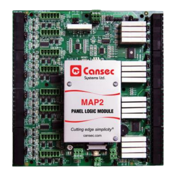
MAP2 to H1000 Panel Communication LEDs If the MAP2 elevator control panel has been correctly configured as a 32 to 64 floor elevator system, the two LEDs on the Panel Logic Module (PLM) daughter board will indicate the RS485 communication to the auxiliary H1000 panels. The PLM LEDs are labeled TX485 (Green LED1) and RX485 (Red LED2). -
Page 14: H1000 Ex1000 Communication
TX485 - LED2. The green TX RS485 LED will only toggle when the address of the Auxiliary H1000 is sent from the MAP2 elevator control panel. When the auxiliary H1000 receives this poll it will send the response to the MAP2 elevator control panel. See previous section which describes the “MAP2 PLM Communication”... -
Page 15: Connection To The Elevator Controls
H1000 outputs. It is important to understand that the MAP2 or H1000 panel’s output relays (“Form C”) will be controlling the coils of the relays in the interface box and that a single shielded single pair must be used for each relay connection. -
Page 16: Host Communication Wiring
Host Communication Wiring The MAP2 elevator control panel is equipped with an Ethernet RJ45 jack (see image below) to allow easy connection for communication with the host. Wiegand-Compatible Reader Wiring The elevator reader, which is mounted in the elevator cab, can read a standard 26-bit or Cansec 37-bit Wiegand proprietary format card or the HID Corporate 1000 format card.
Need help?
Do you have a question about the MAP2 and is the answer not in the manual?
Questions and answers