
Related Manuals for AEI PROTECT-ON SYSTEMS DK-2836A


Summary of Contents for AEI PROTECT-ON SYSTEMS DK-2836A
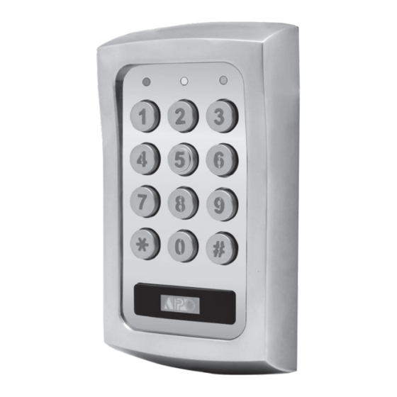
- Page 1 VANDAL RESISTANT TRI-TECH ACCESS CONTROL KEYPAD WITH CARD READER DK-2836A & B User Manual (MK-II) FOR ELECTRIC LOCK, INTER-LOCK AND SECURITY SYSTEM INSTALLATIONS AEI PROTECT-ON SYSTEMS LIMITED www.apo-hk.com Ver.201710_V5...
-
Page 2: Table Of Contents
TABLE OF CONTENTS INTRODUCTION ······································································································································· 4 FEATURES ················································································································································ 4 OPTIONAL DEVICES FOR SYSTEM EXPANSION ·················································································· 5 SPECIFICATIONS ···································································································································· 6 INSTALLATION ········································································································································· 7 Precautions ············································································································································ 7 CONNECTION TERMINALS ··············································································································· 8-10 OTHER FACILITIES ································································································································ 11 On-Board LED Indicators ······················································································································· 11 Pacifier Tone & The LED Signals ···········································································································... - Page 3 Operation Modes ···································································································································· 42 AUXILIARY INFORMATION Close The Programming Mode ················································································································ 42 DRY CONTACT PROGRAMMING MAKE SIMPLE - For General Users ····································································· 43-44 A dry contact means that no electricity is connected to it. It is prepared for free connections. The ································································································...
-
Page 4: Introduction
Independent control for the two output relays with programming timer (DK-2836A) Total 1,100 User Codes / Cards for controlling of the two outputs (DK-2836A) Indoor or outdoor installation with IP-65 all weather ingress protection Stainless steel faceplate combines with die-casting metal back-lit key buttons... -
Page 5: Optional Devices For System Expansion
Wiegand and RS-232 data outputs for the custom projects with external controller and PC. (E) OUTPUT 2 (DK-2836A) ( i ) Shunting an N.C. Zone Please contact your local agent for the optional devices. -
Page 6: Specifications
Output 1 – 1,000 (Codes and/or Cards) + 50 Duress Codes Door Forced-open Alarm -- The keypad will Output 2 – 100 (Codes and/or Cards) + 10 Duress Codes (DK-2836A) generate alarm instantly if the door is forced to Proximity Card: open. -
Page 7: Installation
4) Split-decoded Multi-station Access Control Door Lock INSTALLATION Description ASSEMBLY This is an expansion of application (3). The DK-2836 is expandable to a multi-station system in Split-decoded operation. It is compatible with the auxiliary readers AR-2802 and the auxiliary reader-keypads AR-2806, AR-2807 & AR-2809. Total 3 auxiliary readers or reader-keypads can be connected in parallel with the Data I/O Bus. -
Page 8: Connection Terminals
DATA I/O BUS ELECTRIC LOCK (–) COMMON GND 5 -6 : OUTPUT 2 (Output Relay 2) (+) POWER SUPPLY a) Standard Version (DK-2836A) This is an auxiliary relay output with 2 Amp rating Normally Open NOTE: 1N4004 CATHODE Connect the 1N4004 as close as possible to the lock in (N.O.) or Normally Closed (N.C.) dry contacts controlled by the group... -
Page 9: System Refreshing With "Refreshing Code
7 : ALM O/P (Alarm Output) 2) Multi-station Access Control Door Lock An NPN transistor open collector output with maximum power rating of 24VDC/100mA sink. It is equivalent to an N.O. (Normally Open) terminal referring to ground. It is prepared for triggering an N.O. Description protection zone of an alarm system. - Page 10 1) Dual-station Access Control Door Lock 13 : DOOR SENS (Door Position Sensing Input -- Normally Close) Description A Normally Closed (N.C.) sensing point referring to (-) ground, with the help of a normally closed Owner can select an auxiliary reader AR-2802 or an auxiliary reader-keypad AR-2806, AR-2807 magnetic contact monitors the open or close status of the door.
-
Page 11: Other Facilities
The Split-decoders (Optional) OTHER FACILITIES DA-2800 DA-2801 ON-BOARD LED INDICATORS RED / GREEN (Right) --- It lights up in Green for Output 1 activation; Red for Output 1 inhibited and flashing during inhibition paused. AMBER (Centre) --------- It flashes in Standby. It shows the system status in synchronization with the beep tones. -
Page 12: Preparation For Programming
APPLICATION EXPANSIONS PREPARATION FOR PROGRAMMING Apart from standard-alone operation, DK-2836 is expandable to be a Multi-station System or a High A) CRITERIA FOR CODES AND CARDS Security Multi-station Split-decoded System with its Data I/O Bus for the connection of the optional auxiliary keypad(s) and decoder. -
Page 13: C) List Of User Information
2) INTER-LOCK SYSTEM USING TWO KEYPADS 5) EM Card + Proprietary Secondary User Code – Operation Media 3 The keypad accepts programming with each card having its own proprietary user code to work. It prevents any other people can use the lost card to open the door. Card with proprietary user code approach is ideal for the area that high security is the main concern. -
Page 14: Programming And Operation
PROGRAMMING & OPERATION APPLICATION EXAMPLES POWER-UP THE KEYPAD 1) STAND ALONE DOOR LOCK The keypad gives power-up delay of 1 minute after power has been applied. It is the time frame designed for setting the keypad to programming mode with DAP code. See the details of “DAP CODE –... -
Page 15: Direct Access To Programming Mode With The "Dap" Code - 2 8 2 8
Mode = 1, FUNCTION MODE: Pacifier Tone ON-OFF 0---OFF Pacifier Tone DIRECT ACCESS TO PROGRAMMING MODE WITH “DAP” CODE -- 2 8 2 8 FUNCTION MODE 1---ON In case the Master Code is forgotten, apply the following procedures precisely to set keypad FUNCTION MODE: Mode = 1 into programming mode with DAP code:... -
Page 16: The Default Values After Refreshing
PROGRAMMING SUMMARY CHART THE DEFAULT VALUES AFTER REFRESHING ENTRY LIMITS & CODE FACTORY FUNCTION CODE ENTRY LOCATION LOCATION PARAMETERS DEFAULT FUNCTIONS & VALUES DEFAULT OPTIONS Master Code 0 0 0 0 Factory Set, Not a default value * Master Code 4-8 Digits ... -
Page 17: Master Code
5) Record an “EM Card + User Code” to Operate The Output 1 for Door Open MASTER CODE (Location 01) READ CARD LOCATION MASTER CODE VALIDATION (a) 10 = Programming Location for Output 1 ... -
Page 18: Operation And Functions Of The Super User Code
PROGRAMMING MAKE SIMPLE – For General Users OPERATION AND FUNCTIONS OF THE SUPER USER CODE This is a multi purpose keypad. It has many functions for user’s selection. For those general users 1) Operate Output 1 and 2 taking the keypad for door strike only, most of the features can be kept in their Default values. Only The operation of the Super User Code is just like a normal User Code. - Page 19 OPERATION MODES (Location 94) REMARK : The keypad is programmable for keypad mode to work stand-alone for door control directly or for While SUPER USER CODE is in operation to hold the door lock open, the functions that rely server mode to work with a split-decoder for high security access control.
-
Page 20: Common User Codes For Output 1 & 2
NOTE: 1) Momentary Contact -- The Egress Delay starts to count when the egress button is momentarily COMMON USER CODES FOR OUTPUT 1 & 2 (Locations 03 & 04) pressed. Output 1 activates automatically (door is released) when the delay time reaches. The Common User Codes 1 and 2 are prepared for operating of the Output 1 and 2 respectively as Holding Contact -- The user MUST hold the egress button in contact for the whole period of the an enhance code. -
Page 21: User Codes/Card For Output 1
EGRESS DELAY , WARNING AND ALARM (Location 90) USER CODES / CARDS FOR OUTPUT 1 & 2 (Locations 10 & 20) LOCATION CONFIGURATIONS DELAY TIME VALIDATION LOCATIONS MEDIA USER ID CARD / USER CODE VALIDATION (1) LOCATION ... -
Page 22: Examples - Programming And Operation
EXAMPLES – PROGRAMMING AND OPERATION High Traffic Passage: 1) Example 1 -- EM Card Only : A short buffer time may be necessary for opening a door outward after pressing the egress button for those exits open to a high traffic passage. An egress button with short delay and warning beeps i) Programming : helps the user to pay attention to the people passing by to prevent hitting them when the door is Read Card... - Page 23 INTELLIGENT EGRESS BUTTON – AN UNIQUE FEATURE OF THE KEYPAD 3) Example 3 -- EM Card + Secondary User Code i) Programming : INTRODUCTION Most of the keypads for access control are just for controlling “Going In” from outside. It is not Read Card enough for today’s access control systems.
- Page 24 DOOR FORCED OPEN WARNING & TIMING (Location 80) 5) Example 5 -- Delete An User Code & / or EM Card (for O/P 1 or 2) : i) Delete An User Code or A Lost EM Card LOCATION FUNCTION MODES VALIDATION User ID ...
-
Page 25: Visitor Codes (For Output 1 Only)
OUTPUT OPERATION ANNOUNCER (Location 72) VISITOR CODES (FOR OUTPUT 1 ONLY) (Location 40) The Visitor Codes are temporary user codes for Output 1 (mainly for door strike in access control). LOCATION FUNCTION MODES VALIDATION They can be programmed as “One Time Codes” or “Codes with Time Limit”. The Visitor Codes ... -
Page 26: User Code Entry Mode - Auto Or Manual
EXAMPLES: USER CODE ENTRY MODE – Auto or Manual (Location 70) Example 1: Set a “One Time Visitor Code” with the number of “1 2 6 8” for the Output 1 LOCATION ENTRY MODES VALIDATION (1) LOCATION ... -
Page 27: Duress Codes (For Outputs 1 & 2 )
PERSONAL SAFETY AND SYSTEM LOCK-UP (Location 60) DURESS CODES (FOR OUTPUTS 1 & 2) (Locations 41 & 42) Duress Codes are prepared for those Important Persons in case of DURESS while he is operating LOCATION LOCK-UP OPTIONS VALIDATION the access control keypad. The duress code operates like a normal User Code for Output 1 or 2, and ... -
Page 28: Operation And Function Of The Duress Code
Programming and Operation Examples: EXAMPLES: (i) Set the starting and stopping time for the real-time inhibition period Example 1: Set a “Duress Code” with the number of “3 3 6 9” for Output 1 a) Set Inhibition Period from 12:30 PM (today) – 1:30 PM (same day) for lunch time: ... - Page 29 START & STOP TIMES FOR DAILY INHIBITION OF OUTPUT 1 (Location 56) Report Duress in EM Card Operation Setting with start and stop times into the keypad, the real-time inhibition period for output 1 will The Duress Codes are Prime User Codes in the system. In the “EM Card + Secondary User Code” recycle daily until the time settings are cleared.
-
Page 30: Output Modes & Timing For Output 1 And 2
SYSTEM REAL-TIME-CLOCK (Location 55) OUTPUT MODE & TIMING FOR OUTPUT 1 and 2 (Locations 51 & 52) This 24 hour real-time-clock provides the daily time base for starting and stopping the function of The two relay outputs are programmable for Start/Stop or Timing modes. Apart from door access inhibition to relay output 1 (mainly for electric door lock strike).
Need help?
Do you have a question about the DK-2836A and is the answer not in the manual?
Questions and answers