Advertisement
Quick Links
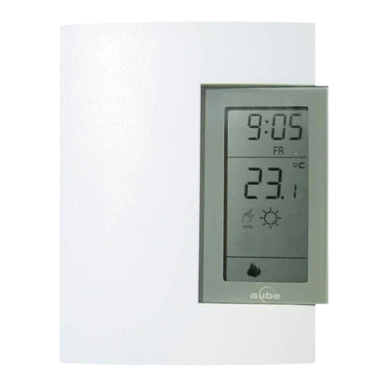
Installation
1.1
Remove the old thermostat
Cut the power source to your heating or air conditioning system.
Remove the cover of the old thermostat.
CAUTION: If, upon removing the wall plate, you see that it is mounted on
a junction box (similar to the junction box located behind an electrical
switch or outlet), this may indicate that it is a 120-V / 240-V system. For
more security, consult a qualified electrician to check the installation.
1.2
Install the new thermostat
For a new installation, choose a location about 1.5 meters (5 feet) above
the floor, with good air circulation. The thermostat must be installed on an
inside wall.
Avoid locations where there are:
•
air drafts (top of a staircase, air outlet,...)
•
dead air spots (behind a door,...)
•
direct sunlight
•
concealed chimneys or stove pipes.
1.3
Install and connect the thermostat
Loosen the captive screw holding the faceplate to the mounting
plate.
Pull the lower part to separate the faceplate from the mounting plate.
Fix the mounting plate onto the wall using the supplied screws.
1.4
Identify the wires
If the wall plate of your old thermostat has more than two wires
coming out of the wall, you will need to label the wires. Start by
identifying the letters close to each screw or terminal on which a wire
is connected. These terminals may be located on either side of the
plate.
Disconnect and identify each wire*.
You may need to tape the wires to the wall to keep them from falling
back into it. If the wall opening is bigger than necessary, fill it with
insulating wool in order to prevent the infiltration of warm or cold air
behind the thermostat.
* If your installation is recent, the colour of the wires should match the
identification on the mounting plate.
(Rh) Red
Heating power source
(W) White
Heating relay
(Rc) Blue
Air conditioning power supply
(Y) Yellow Air conditioning relay
(G) Green Fan relay
TH141-HC-28
1.5
Connect the labelled wires to the thermostat
1.
Connect the system wires to the thermostat terminals according to
one of the wiring diagrams in section 1.6.
Make sure to return the remaining wire length into the wall.
If you own a CT240 telephone controller, refer to section 6.1 for
connection.
1.6
Wiring diagrams
The TH141 thermostat is compatible with most heating and air
conditioning systems. Multi-level heating and air conditioning systems,
Millivolt control heating systems, heat pumps and baseboard heating
units are not compatible with this thermostat. Baseboard units can be
connected using a 24-V relay.
1.6.1 2-wire heating system
Connect the heating relay to terminal W.
Connect the 24-V transformer to terminal
Rh.
In this case, the order of connection is
unimportant.
1.6.2 3-wire heating system with fan control
Connect the heating relay to terminal W.
Connect the fan relay to terminal G.
Connect the 24-V transformer to terminal
Rh.
Connect a wire between terminals Rh and
Rc.
1.6.3 3-wire air conditioning system with fan control
Connect the air conditioning relay to
terminal Y.
Connect the fan relay to terminal G.
Connect the 24-V transformer to terminal
Rc.
1.6.4 4-wire heating and air conditioning system
Connect the heating relay to terminal W.
Connect the air-conditioning relay to
terminal Y.
Connect the fan relay to terminal G.
Connect the 24-V transformer to terminal
Rh.
Connect a wire between terminals Rh and Rc.
1.6.5 5-wire heating and air-conditioning system
Connect the heating relay to terminal W.
Connect the air-conditioning relay to
terminal Y.
Connect the fan relay to terminal G.
Connect the 24-V heating transformer to
terminal Rh.
Connect the 24-V air conditioning transformer to terminal Rc.
TH141-HC-28
400-141-000-B
2008-02-01
User Guide
1/4
Advertisement

Subscribe to Our Youtube Channel
Related Manuals for Aube Technologies TH141-HC-28


Summary of Contents for Aube Technologies TH141-HC-28
- Page 1 TH141-HC-28 User Guide Connect the labelled wires to the thermostat Installation Connect the system wires to the thermostat terminals according to Remove the old thermostat one of the wiring diagrams in section 1.6. Make sure to return the remaining wire length into the wall.
- Page 2 Radiant or convection electric heating cases (reduction for heating temperature, increase for air-conditioning), you must program the settings for heating and then for air-conditioning. • 15-minute cycle: Central heating and air-conditioning unit • 20-minute cycle: Commercial unit TH141-HC-28 400-141-000-B 2008-02-01...
- Page 3 Manual/Auto button. If select all days of the week by pressing on the Day button for 3 you wish to immediately return to the programmed settings, press the seconds. Manual/Auto button twice. TH141-HC-28 400-141-000-B 2008-02-01...
- Page 4 Vacation button of the telephone controller again. The red light will go off and the icon will disappear from the thermostat within a For more information on our products, go to maximum of 5 seconds. www.aubetech.com To modify the Vacation setting, refer to section 2.2. TH141-HC-28 400-141-000-B 2008-02-01...
Need help?
Do you have a question about the TH141-HC-28 and is the answer not in the manual?
Questions and answers