Advertisement
Quick Links
Instruction Manual
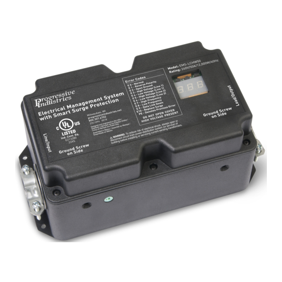
Electrical Management System (EMS)
EMS-LCHW30 & EMS-LCHW50
EMS-LCHW50
EMS-LCHW30
These instructions are intended to provide assistance with the installation
!
CAUTION
of this product, and are not a substitute for a more comprehensive understanding
of electrical systems. We strongly recommend that a certified electrician perform the
installation of this product. Improper installation may void warranty.
Advertisement

Summary of Contents for Progressive Industries EMS-LCHW50
- Page 1 Instruction Manual Electrical Management System (EMS) EMS-LCHW30 & EMS-LCHW50 EMS-LCHW50 EMS-LCHW30 These instructions are intended to provide assistance with the installation CAUTION of this product, and are not a substitute for a more comprehensive understanding of electrical systems. We strongly recommend that a certified electrician perform the...
- Page 2 L-N, L-G, and N-G. Total Joule rating is 1,790J and 44,000A surge current. Response time <1 Nano second. • 5-Mode Surge Protection (EMS-LCHW50): This feature provides full surge protection L-N, L-N, L-G, L-L, and N-G. Joule rating is 3,580J and 88,000A surge current.
- Page 3 DO NOT USE as it could result in possible melting of the RV power plug. • Progressive Industries recommends you have a certified electrician perform the installation of the EMS unit. • All AC power extension cords in conjunction with your EMS unit should be rated 10 gauge for 120V, 30A systems or 6 gauge for 240V, 50A systems and rated for outdoor use to reduce the risk of electrical shock.
- Page 4 INSTRUCTION MANUAL: ELECTRICAL MANAGEMENT SYSTEM (EMS) Installation Instructions Before Transfer Box Visual Photo Library - LCHW50C: page 9 | LCHW30C: page 10 Wiring Diagram - LCHW50C: page 11 | LCHW30C: page 11 For installation, in addition to the EMS Kit, you will need: •...
- Page 5 INSTRUCTION MANUAL: ELECTRICAL MANAGEMENT SYSTEM (EMS) 10) Secure cable ends by tightening down strain reliefs ove the input and output wires. Do not over tighten as this could cut through the insulation and cause a short. 11) Set time delay jumper on the circuit board. The factory setting is for 15 seconds. Remove jumper to set for 136 seconds (02:16).
- Page 6 INSTRUCTION MANUAL: ELECTRICAL MANAGEMENT SYSTEM (EMS) 8) Take the jumper cable and connect it to the input side by sliding through the wire restraint on the end of the EMS control box and then connect the black wire to L1; white to L2;...
- Page 7 E 8 - Line Frequency Low (line frequency below 51 cycles per second) E 9 - Data Link Down (call technical support) E10 - Replace Surge Protector Module (call technical support) * Codes only apply to EMS-LCHW50 models ProgressiveIndustries.net | 800.307.6702...
-
Page 8: Troubleshooting Guide
EMS will cause the device to malfunction. If the EMS is still not functioning at this point, follow instructions below prior to calling Progressive Industries Technical Support. In order for the on-call Technician to help troubleshoot the problem(s) you are experiencing and render the best possible solution, it is necessary you be at your RV when you place your call. - Page 9 INSTRUCTION MANUAL: ELECTRICAL MANAGEMENT SYSTEM (EMS) Visual References Photo Library for the EMS-LCHW50 ProgressiveIndustries.net | 800.307.6702...
- Page 10 INSTRUCTION MANUAL: ELECTRICAL MANAGEMENT SYSTEM (EMS) Photo Library for the EMS-LCHW30 ProgressiveIndustries.net | 800.307.6702...
- Page 11 INSTRUCTION MANUAL: ELECTRICAL MANAGEMENT SYSTEM (EMS) Wiring Diagram for EMS-LCHW50 Input Output Sensor White White Input Output Relay Black Black (Contactors) Input Output Sensor w/green mark Input Output Ground Ground Wiring Diagram for EMS-LCHW30 White White Input Output Relay (Contactors)
- Page 12 INSTRUCTION MANUAL: ELECTRICAL MANAGEMENT SYSTEM (EMS) Progressive Industries, Inc. For more information regarding the Limited Lifetime Warranty, Troubleshooting and the Warranty Claim Form visit: www.progressiveindustries.net Technical Support • 800.307.6702 • tech.progressive@oneasg.com ProgressiveIndustries.net | 800.307.6702 | ZX481/PRI-6007 (1221)


Need help?
Do you have a question about the EMS-LCHW50 and is the answer not in the manual?
Questions and answers
Just bought this motorhome that has this model lchw50 and the display is black when plugged into a 50 amp I have 240 going in and nothing going out what do I have to do