
Subscribe to Our Youtube Channel
Related Manuals for Circor Contromatics M6 Series


Summary of Contents for Circor Contromatics M6 Series
- Page 1 Installation, Operation, and Maintenance Manual for the Contromatics M6 Series RACK AND PINION PNEUMATIC ACTUATORS Edition...
-
Page 2: Table Of Contents
6th EDITION M6 SERIES IOM ISSUED 12/2014 TABLE OF CONTENTS I. Introduction................... 04 Storage....................Pg.04 II. Identification................05 A. General Identification..............Pg.05 B. Actuator Part Identification............Pg.06 III. Specification................07 A. Actuator Weights................Pg.07 B. Air Volume and Consumption............Pg.07 C. - Page 3 6th EDITION M6 SERIES IOM ISSUED 12/2014 TABLE OF CONTENTS XI. Torque Charts ................31 A. Double Acting................Pg.31 B. Spring Return................. Pg.31 XII. Dimensional Information..................34 XIV. Warranty ........................35...
-
Page 4: Introduction
6th EDITION M6 SERIES IOM ISSUED 12/2014 I. Introduction Contromatics offers one of the largest ranges of pneumatic rack and pinion actuators on the market. Contromatics actuators are designed to operate with pressurized air, but will function equally as well with hydraulic fluid, water or inert fluids. -
Page 5: Identification
6th EDITION M6 SERIES IOM ISSUED 12/2014 II. Identification A. General Identification Fig. 2.2 Fig. 2.1 Fig. 2.3 Fig. 2.4 Fig. 2.5 1: Top auxiliaries interface. (VDI/VDE 3845; NAMUR) 2: Solenoid interface (VDI/VDE 3845; NAMUR) 3: Valve interface (ISO 5211, DIN 3337 patterns/w UNC threads) 4: Spring return actuator (Closed) 5: Double Acting actuator (Open) 6: Actuator Serial Number... -
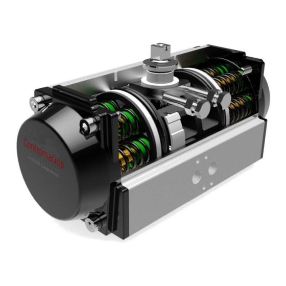
Page 6: Actuator Part Identification
6th EDITION M6 SERIES IOM ISSUED 12/2014 B. Actuator Part Identification ITEM # Description Material Left End Cap ASTM 384 Cast Aluminum Body 6005T5 Extruded Aluminum Upper Pinion O-Ring Flange Bearing Delrin Pinion Washer Stainless Steel Pinion Circlip Stainless Steel Indicator Indicator Screw Piston... -
Page 7: Specification
6th EDITION M6 SERIES IOM ISSUED 12/2014 III. Specification A. Actuator Weights "M" Series Weights (lbs) Size Weight For DA Weight For K55 Single Spring Weight 3.00 3.30 0.03 4.65 5.05 0.04 5.75 6.25 0.05 7.65 8.65 0.10 1030 10.45 11.95 0.15 1400... -
Page 8: Speed Of Operation
6th EDITION M6 SERIES IOM ISSUED 12/2014 C. Speed of Operation* M Series Speed of Operation (sec) Double Acting Models Spring Return Models Size Openi ng Stroke Closing stroke Per cycle Openi ng Stroke Closing stroke Per cycle 1030 1400 2200 2900 4100... -
Page 9: Operation
6th EDITION M6 SERIES IOM ISSUED 12/2014 IV. Operation A. Principals of Operation (Double Acting) The Contromatics pneumatic actuator has simple operational characteristics. Port A is connected to the interior cavity between the pistons. Port B is connected to the end cap cavities (See Figures 4.1-4.2 below). If port A is pressur- ized (Fig. -
Page 10: Fail Positions
6th EDITION M6 SERIES IOM ISSUED 12/2014 C. Fail Positions The Contromatics actuator standard operation is counterclockwise to open and clockwise to close. This is referred to as a “fail clockwise” configuration or FCW. However, it is also available in an FCCW or “fail counterclockwise”... -
Page 11: Mounting And Installation
6th EDITION M6 SERIES IOM ISSUED 12/2014 V. Mounting and Installation A. Actuator Mounting Specifications The Contromatics actuator is designed to be easily installed. The standard M6 series comes with an ISO bottom mounting pattern and double square drive on the pinion allowing for simpler coupling fabrication. Additional valve mounting patterns are available upon request. -
Page 12: Travel Stop Adjustment
6th EDITION M6 SERIES IOM ISSUED 12/2014 VI. Travel Stop Adjustment Contromatics actuators have open and close travel stops for +5°/-5° of travel. A. Setting The Stops on Double Acting Units 1. Operate the actuator assembly to the closed position. 2. -
Page 13: Setting The Stops On Spring Return Units (Fail Closed)
6th EDITION M6 SERIES IOM ISSUED 12/2014 B. Setting The Stops on Spring Return Units (Fail Closed) 1. Remove the air supply to the A port. Actuator will move to the closed position. Please note the position of the actuator. 2. -
Page 14: Setting The Stops On Spring Return Units (Fail Open)
6th EDITION M6 SERIES IOM ISSUED 12/2014 C. Setting The Stops on Spring Return Units (Fail Open) 1. Remove/lockout the air supply to the actuator and it will drive to the open position. Note the position of the actuator. 2. Apply air to close the actuator. Note the position of the actuator while the air supply is maintained, loosen the locknut on the open stop and adjust the stop to the correct position desired. -
Page 15: Actuator Disassembly
6th EDITION M6 SERIES IOM ISSUED 12/2014 VII. Actuator Disassembly A. Steps to Actuator Disassembly 1. Disconnect all electrical and air supplies from the actuator. 2. Ensure the actuator is depressurized and in the fail position. 3. Remove actuator from mounting bracket and coupling, and any limit switches, manual overrides, positioners and other pneumatic accessories (where applicable), and place in a clean environment. - Page 16 6th EDITION M6 SERIES IOM ISSUED 12/2014 5. Remove any springs and repeat for the other side. Spring Cartridges Fig. 7.2 6. Loosen both limit stop nuts then remove both limit stop bolts to allow full rotation of the pinion. op Bolts Fig.
- Page 17 6th EDITION M6 SERIES IOM ISSUED 12/2014 7. Rotate the pinion counterclockwise to push the pistons away from each other until they completely disengage from the pinion. (NOTE: This is for standard FCW configuration actuators. For non-standard units rotation may be reversed.
- Page 18 6th EDITION M6 SERIES IOM ISSUED 12/2014 10. Slide pinion down through the bottom of the actuator until you can remove the pinion cam, thrust bearing, and upper pinion o-ring from the top of the pinion. Note the orientation of the pinion cam so it can be replaced in the same position during reassembly.
-
Page 19: Maintenance And Temperature Change
6th EDITION M6 SERIES IOM ISSUED 12/2014 Maintenance and Temperature Change A. Repair Kit Overview Any time maintenance is preformed on an actuator, it is necessary to replace all O-rings, grease, and bearings to insure the longest life. During maintenance all parts should be wiped clean of grease using a clean cloth, and parts should be lubricated with the fresh grease for the correct temperature application before reassembly. -
Page 20: Installing Repair Kits Or Changing Temperature Rating
6th EDITION M6 SERIES IOM ISSUED 12/2014 B. Installing Repair Kit or Changing Temperature Rating Follow the listed steps to install a repair kit or change temperature applications. For reference the various temperature specifications and materials can be found on pg. 9 of this manual. 1. -
Page 21: Actuator Assembly
6th EDITION M6 SERIES IOM ISSUED 12/2014 VIII. Actuator Assembly A. Steps to Actuator Assembly The directions below assume the actuator has been disassembled. Please refer to pg. 21 if this process has not been completed. 1. Inspect all wear surfaces for excessive wear or possible damage. 2. - Page 22 6th EDITION M6 SERIES IOM ISSUED 12/2014 Fig. 9.6 Fig. 9.7 5. Press the top pinion o-ring into the inset around the top of the pinion then install the flange bearing and top pinion washer (Fig. 9.6). Use a pair of circlip pliers to install the pinion circlip (Fig. 9.7) Be careful not to expand the circlip too much as it may be damaged if over expanded.
- Page 23 6th EDITION M6 SERIES IOM ISSUED 12/2014 8. Rotate the pinion to the open position. Orient the pistons correctly according to your operation type and slide them into the body until both racks engage with the pinion. (For correct orientation of pistons refer to p.34 of this manual) 9.
- Page 24 6th EDITION M6 SERIES IOM ISSUED 12/2014 10. After you have ensured the pistons are correctly installed in the actuator, move the actuator to the open position, set the open stop the same way as the closing stop in step 8, then close the actuator. 11.
- Page 25 6th EDITION M6 SERIES IOM ISSUED 12/2014 12. After ensuring the end cap O-ring is in place and lubricated, place the end cap on the actuator and tighten it using the end cap screws. Tighten the screws incrementally in the pattern shown below (Fig. 9.14) to evenly seat the end cap onto the actuator, then repeat this for the opposing end cap.
-
Page 26: Spring Configuration
6th EDITION M6 SERIES IOM ISSUED 12/2014 B. Spring Configurations The Contromatics M series actuator uses fully encapsulated, preloaded spring cartridges that are easily configured for adjustable spring return torque. While DA (double acting) refers to an actuator without springs, the letter “K” followed by the number of springs in each end cap is used for the different spring configurations. -
Page 27: Air Leak Testing
6th EDITION M6 SERIES IOM ISSUED 12/2014 C. Air Leak Test Any time the actuator is modified or undergoes maintenance, a leak test needs to be completed to insure the actuator is air tight and working correctly. To perform an air leak test: 1. - Page 28 6th EDITION M6 SERIES IOM ISSUED 12/2014 D. Changing Fail Configurations Follow these steps to change the fail configuration of the actuator: 1. Disassemble the actuator as described on pg.21 steps 1-7. 2. Using the proper size crescent wrench, rotate the pinion to its new orientation when in the “fail” position (actuator closed), and set the new closed stop.
-
Page 29: Automation Accessories
6th EDITION M6 SERIES IOM ISSUED 12/2014 IX. Automation Accessories A. Speed Control The Speed Control (UT-SC) The Tamper Resistant Speed Control (UT-SC-TR) The Speed Controller accurately adjusts the speed of the actuator for precise control of the open/close speed for the valve. The UT-SC can be mounted directly on the actuator or can be used with a Namur solenoid valve and/or positioner. -
Page 30: Airlock
6th EDITION M6 SERIES IOM ISSUED 12/2014 C. Airlock The Airlock (UT-AL) The UT-AL airlock “block and vent” device blocks the supply of air from both the solenoid valve and the actuator while it vents all compressed air from the actuator. This allows for safer operation when manual control of the valve is necessary. - Page 31 6th EDITION M6 SERIES IOM ISSUED 12/2014 X. Series Torque Information M Series Double Acting Torques (in-lbs) Air Supply Pressure Contromatics 30PSI 40PSI 50PSI 60PSI 70PSI 80PSI 90PSI 100PSI 110PSI 120PSI Size 1014 1107 1030 1088 1224 1360 1496 1632 1400 1181 1377...
- Page 32 6th EDITION M6 SERIES IOM ISSUED 12/2014 M Series Spring Return Torques (in-lbs) Actua tor Ai r Torques Actua tor Spri ng Contro Spri ng Torques 40PSI 60PSI 80PSI 100PSI 120PSI Si ze Des i gna ti on Sta rt Sta rt Sta rt Sta rt...
- Page 33 M6 SERIES IOM 6th EDITION ISSUED 12/2014 M Series Spring Return Torques (in-lbs) Actuator Air Torques Actuator Spring Contro Spring Torques 40PSI 60PSI 80PSI 100PSI 120PSI Size Designation Start Start Start Start Start Start 5371 5002 8520 8150 11668 11299 14817 14447 17965...
- Page 34 6th EDITION M6 SERIES IOM ISSUED 12/2014 XI. Dimensional Information SIZE 5.79 3.15 2.82 3.62 2.83 0.79 (20mm) 1.417 (F03)* # 10-32 UNF* 1.969 (F05)* 1/4-20 UNC* 3.15 2.58 0.59 2.09 1.61 0.433 (11mm) 6.69 3.50 3.30 4.24 3.46 0.79 (20mm) 1.969 (F05) 1/4-20 UNC 2.756 (F07) 5/16-18 UNC 3.15...
- Page 35 EVENT SHALL SELLER BE LIABLE FOR ANY DIRECT, INCIDENTAL OR CONSEQUENTIAL DAMAGES OF ANY NATURE, OR LOSES OR EXPENSES RESULTING FROM ANY DEFECTIVE PRODUCTS OR THE USE OF ANY PRODUCT. For questions or more information, visit www.circorenergy.com or email us at Sales@circorenergy.com CIRCOR | Contromatics Email: sales@circorenergy.com...
Need help?
Do you have a question about the Contromatics M6 Series and is the answer not in the manual?
Questions and answers