Table of Contents
Advertisement
Einbau- und Betriebsanleitung
Installation and Operating Instructions
Instructions de montage et de service
Elektrischer Stellantrieb
Electric Actuator
Servomoteur électrique
Inhaltsverzeichnis
1
2
3
4
5
6
7
8
9
10
11
12
13
14
Content
1.
2
3
4
5
6
7
8
9
10
11
12
13
14
Index
1
2
3
4
5
6
7
8
9
10
11
12
13
14
1
2
3
4
Seite
- 2 -
- 2 -
- 2 -
- 2 -
- 3 -
- 3 -
- 3 -
- 3 -
- 4 -
- 4 -
- 4 -
- 4 -
- 4 -
- 5 -
- 5 -
- 5 -
- 5 -
- 6 -
- 6 -
- 6 -
- 6 -
- 6 -
- 7 -
- 7 -
- 7 -
- 7 -
- 7 -
- 8 -
- 8 -
- 8 -
- 9 -
- 9 -
- 9 -
- 9 -
- 9 -
- 10 -
- 10 -
- 10 -
- 10 -
- 10 -
- 11 -
- 11 -
- 12 -
- 12 -
- 13 -
- 15 -
- 19 -
REact 30 - 8010
Baureihe / Series / Séries
REact 30E; REact 30DC
10/2018
Advertisement
Table of Contents

Related Manuals for Circor RTK REact 30 Series


Summary of Contents for Circor RTK REact 30 Series
-
Page 1: Table Of Contents
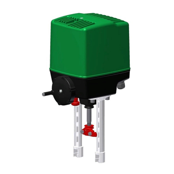
Einbau- und Betriebsanleitung REact 30 - 8010 Installation and Operating Instructions Instructions de montage et de service Baureihe / Series / Séries Elektrischer Stellantrieb REact 30E; REact 30DC Electric Actuator Servomoteur électrique Inhaltsverzeichnis Seite Anbau auf Armaturen - 2 - Einbaubedingungen - 2 - Gefahrenhinweise... -
Page 2: Anbau Auf Armaturen
Einbau- und Betriebsanleitung REact 30 - 8020 Installation and Operating Instructions Instructions de montage et de service Anbau auf Armaturen Der Anbau auf die Armatur kann in beliebiger Lage erfolgen, jedoch nicht nach unten hängend. Die Kegelkupplung ist standardmäßig mit einem M12 Anschlussgewinde ausgeführt. -
Page 3: Elektrischer Anschluss
Einbau- und Betriebsanleitung REact 30 - 8030 Installation and Operating Instructions Instructions de montage et de service • Der Elektromotor kann in diesem Antrieb bei höherer Umgebungstemperatur (Grenze: siehe techn. Daten) betrieben werden. Elektrischer Anschluss Beim elektrischen Anschluss des Stellantriebes müssen die Sicherheitsvorschriften beachtet werden. Kontrolle der Stromart, Netzspannung und Frequenz mit den auf dem Typenschild angegebenen Daten. -
Page 4: Heizung
Einbau- und Betriebsanleitung REact 30 - 8040 Installation and Operating Instructions Instructions de montage et de service 8.5 Einstellung Potentiometer Bei der Lieferung des Stellantriebes mit dem Ventil ist das Potentiometer bereits werksseitig eingestellt (Standard: 10% vom max. ohmschen Wert des Potentiometers). Nachträgliche Justierung des Potentiometers: •... -
Page 5: Wartung, Instandhaltung
Einbau- und Betriebsanleitung REact 30 - 8050 Installation and Operating Instructions Instructions de montage et de service • Motorgruppe ersetzen • Neuen Motor befestigen und Stecker anschließen. Wartung, Instandhaltung Der Antrieb ist wartungsfrei. Der Antrieb darf nur mit einer milden Seifenlauge gereinigt werden. Installation onto valves Installation onto valves can be any position except hanging down. -
Page 6: Information
Einbau- und Betriebsanleitung REact 30 - 8060 Installation and Operating Instructions Instructions de montage et de service Hot surface warning Information • The RTK actuators control the control or shut/off valves requiring a linear nominal displacement. Refer to the data sheets or technical data for ratings and applications. -
Page 7: Heater
Einbau- und Betriebsanleitung REact 30 - 8070 Installation and Operating Instructions Instructions de montage et de service The maximum stroke is 40 mm. The top position of the drive screw is shown in Image 8. 8.2 Adjusting the force switch-off The force switch-off is factory preset (operational force/ closing force see: Technical Data, page 14). -
Page 8: Maintenance, Repairs
Einbau- und Betriebsanleitung REact 30 - 8080 Installation and Operating Instructions Instructions de montage et de service • Remove the lever force switch (Image 17, item 510). • Loosen the adapter board (Image 17, item 430) from the board bracket. •... -
Page 9: Indications De Danger
Einbau- und Betriebsanleitung REact 30 - 8090 Installation and Operating Instructions Instructions de montage et de service • Degré de salissure II Indications de danger Avertissement tension électrique dangereuse Référence aux indications de montage et d'installation Avertissement surfaces chaudes Indications •... -
Page 10: Réglage
Einbau- und Betriebsanleitung REact 30 - 80100 Installation and Operating Instructions Instructions de montage et de service Réglage 8.1 Configuration de la course La course maximale est de 40 mm. La position supérieure de la bielle de commande est représentée sur l'image. 8.2 Configuration de la coupure de force La coupure de force est configurée à... -
Page 11: Remplacement De Composants
Einbau- und Betriebsanleitung REact 30 - 80110 Installation and Operating Instructions Instructions de montage et de service Remplacement de composants 13.1 Remplacer la platine de connexion Attention ! Observez les consignes de sécurité Le servomoteur doit être déverrouillé. • Pour procéder au remplacement de la platine, retirer les chariots (ill. 17 pos. 520). •... -
Page 12: Anhang / Appendix/ Annexe
Einbau- und Betriebsanleitung REact 30 - 80120 Installation and Operating Instructions Instructions de montage et de service Anhang / Appendix/ Annexe Technische Daten / Technical specifications / Caractéristiques techniques Type / type / type React 30E -028 -074 -112 Regelkraft / operating force / force de poussé 3,0 kN Schließkraft / closing force / force de fermeture 3,2 kN... -
Page 13: Elektrischer Anschlußplan / Terminal Connection / Schéma De Cablage
Einbau- und Betriebsanleitung REact 30 - 80130 Installation and Operating Instructions Instructions de montage et de service Elektrischer Anschlußplan / Terminal connection / schéma de cablage Motor Th* Th* M1 M2 M3 POT 1 POT 2 Klemme A2* A3* DA WA DZ WZ BLDC BLDC Controller HALL Signal... - Page 14 Einbau- und Betriebsanleitung REact 30 - 80140 Installation and Operating Instructions Instructions de montage et de service POT 1 Stellantrieb/ Actuator REtrans2W 100% 1kΩ Option 20mA REpos Feedback 85 86 mA-Signal REtrans4W or Fieldbus 1kΩ 20mA Spannungsversorgung/ mA / V mA / V Powersupply Input...
-
Page 15: Technische Abbildungen
Einbau- und Betriebsanleitung REact 30 - 80150 Installation and Operating Instructions Instructions de montage et de service Technische Abbildungen Aufbau auf Armatur - Joch/Mounting on a valve – yoke Aufbau auf Armatur - Säulen/Mounting on a valve – pillars Bild 2 Bild 3 Einbau des Antriebes / Installing the actuator / Installation de l'unité... - Page 16 Einbau- und Betriebsanleitung REact 30 - 80160 Installation and Operating Instructions Instructions de montage et de service Handbetätigung / Manual operation / fonctionnement manuel Kraftabschaltung / Force switch / Contacteur de force Bild 6 Bild 7 Einstellung des Hubes/Stroke adjustment//Réglage de la course Einstellung der Wegabschaltung / Stroke adjustment / Contacteur de course Bild 8 Bild 9...
- Page 17 Einbau- und Betriebsanleitung REact 30 - 80170 Installation and Operating Instructions Instructions de montage et de service Potentiometer / Potentiométre REpos Bild 10 Bild 11 Heizung / Heater / Chauffage Stellungsrückmeldemodul für REpos /Position feedback module for REpos/ Retour de position module pour Repos (I/Y-Modul) Bild 12 Bild 13 10/2018...
- Page 18 Einbau- und Betriebsanleitung REact 30 - 80180 Installation and Operating Instructions Instructions de montage et de service RElog REtrans Bild 14 Bild 15 Montage der BLDC-Motorgruppe Bild 16 4x Linsenschraube / screw / vis M4x10 BLDC-Controller / contrôleur 4x Abstandsbolzen / distance bolts / boulons d'écartement M4x65 BLDC-Motor...
-
Page 19: Ersatzteilliste / Spare Parts List / Liste De Rechange
Einbau- und Betriebsanleitung REact 30 - 80190 Installation and Operating Instructions Instructions de montage et de service Ersatzteilliste / spare parts list / liste de rechange Bild 17 10/2018... - Page 20 Einbau- und Betriebsanleitung REact 30 - 80200 Installation and Operating Instructions Instructions de montage et de service Bild 18 10/2018...
- Page 21 Einbau- und Betriebsanleitung REact 30 - 80210 Installation and Operating Instructions Instructions de montage et de service 10/2018...
- Page 22 Einbau- und Betriebsanleitung REact 30 - 80220 Installation and Operating Instructions Instructions de montage et de service Order no. Note CGEHR3000009 Gehäuse-Oberteil Housing–upper part Capot CMUSR2000009 Spindelmutter-Gruppe Spindle nut group Ecrou de tige CZRAR2000009 Zahnrad-Gruppe 0 Gear group 0 Roue dentée 0 CZRAR2009009 CZRAR3010009 Zahnrad-Gruppe 1...
- Page 23 Einbau- und Betriebsanleitung REact 30 - 80230 Installation and Operating Instructions Instructions de montage et de service CE-Konformitätserklärung CE-Declaration of Conformity CE.Déclaration de conformité gemäß EG-Richtlinie EMV 2004/108/EG und in acc. with the EMC directive 2004/108/EC suivant les directives EMC 2004/108/CE et Niederspannungsrichtlinie 2014/35/EU and Low-Voltage Equipment Directive les directives 2014/35/EU...
- Page 24 Einbau- und Betriebsanleitung REact 30 - 80240 Installation and Operating Instructions Instructions de montage et de service Technische Änderung vorbehalten/ Subject to technical alteration/ Sous réserve de modifications techniques 10/2018...
Need help?
Do you have a question about the RTK REact 30 Series and is the answer not in the manual?
Questions and answers