
Related Manuals for LAUMAS W200BOX


Summary of Contents for LAUMAS W200BOX
- Page 1 ENGLISH ENGLISH ENGLISH ENGLISH Installation and User Manual version 1.07 W200 Base 2014/30/EU EN55022:2010 EN61000-6-2:2005 EN61000-6-4:2007 SYSTEM IDENTIFICATION...
- Page 2 No guarantee against misuse. Batteries: Laumas provides 1 year guarantee from the date of delivery note, against material defects or battery manufacturing faults. Disposal of Waste Equipment by Users in Private Households in the European Union This symbol on the product or on its packaging indicates that this product must not be disposed of with your other household waste.
-
Page 3: Table Of Contents
TABLE OF CONTENTS USER WARNINGS ......................... 1 RECOMMENDATIONS FOR CORRECT INSTALLATION OF WEIGHING INSTRUMENTS . 1 RECOMMENDATIONS FOR CORRECT INSTALLATION OF THE LOAD CELLS ....1 LOAD CELL INPUT TEST (QUICK ACCESS) ................. 3 LOAD CELL TESTING ......................3 MAIN SPECIFICATIONS OF THE INSTRUMENT..............4 BUFFER BATTERY ........................ - Page 4 WEIGHT READING VIA SERIAL PORT ................26 RS485 CONNECTION ........................26 RS232 CONNECTION ........................27 COMMUNICATION SETTING ......................27 WEIMOD MODE ..........................28 WEIRIP MODE ..........................28 TEST ............................28 DATE AND TIME SETTING ....................29 INFO MENU ..........................29 SETPOINT PROGRAMMING ....................
-
Page 5: User Warnings
USER WARNINGS RECOMMENDATIONS FOR THE PROPER USE OF WEIGHING INSTRUMENT Keep away from heat sources and direct sunlight Repair the instrument from rain (except special IP versions) Do not wash with water jets (except special IP versions) Do not dip in water Do not spill liquid on the instrument Do not use solvents to clean the instrument Do not install in areas subject to explosion hazard (except special Atex versions) - Page 6 CONNECTING SEVERAL CELLS IN PARALLEL: Connect several cells in parallel by using - if necessary - a watertight junction box with terminal box. The cell connection extension cables must be shielded, led individually into their piping or conduit and laid as far as possible from the power cables (in case of 4-wire connections, use cables with 4x1 mm minimum cross-section).
-
Page 7: Load Cell Input Test (Quick Access)
LOAD CELL INPUT TEST (QUICK ACCESS) From the weight display, press ▲ for 3 seconds; the response signal of the load cells is displayed, expressed in mV with four decimals. LOAD CELL TESTING Load cell resistance measurement (use a digital multimeter): - Disconnect the load cells from the instrument and check that there is no moisture in the cell junction box caused by condensation or water infiltration. -
Page 8: Main Specifications Of The Instrument
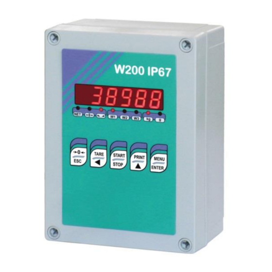
14 mm, 7 segments; 8 indicator LEDs. 5−key membrane keypad with buzzer. Real-time clock/calendar with buffer battery. W200BOX - IP67 waterproof ABS box version: dimensions 170x140x95 mm; four fixing holes Ø 4 mm (centre distance 152x122 mm). W200 IP67 - IP67 waterproof polycarbonate box version: dimensions 180x130x77 mm, four fixing holes Ø... -
Page 9: Technical Specifications
TECHNICAL SPECIFICATIONS POWER SUPPLY and CONSUMPTION (VDC) 12/24 VDC ±10%; 5 W (standard) POWER SUPPLY and CONSUMPTION (VAC) 115/230 VAC (optional); 50-60 Hz; 6 VA NO. OF LOAD CELLS IN PARALLEL and SUPPLY max 8 (350 ohm); 5 VDC / 120 mA LINEARITY / ANALOG OUTPUT LINEARITY <... -
Page 10: Electrical Connections
ELECTRICAL CONNECTIONS TERMINALS LEGEND +SUPPLY (12/24 VDC) OUTPUT No. 5 otherwise: 115/230 VAC optional version: +ANALOG OUTPUT (0÷10 V) +OUTPUT (24 VDC) -SUPPLY (12/24 VDC) RS232, RS485: SHIELD, GND E/EC OPTION: GND E/EC OPTION otherwise: 115/230 VAC optional version: -ANALOG OUTPUT COMMON -OUTPUT (24 VDC) RS232, RS485: SHIELD, GND E/EC OPTION: GND... -
Page 11: Wiring Diagram
WIRING DIAGRAM OUTPUTS INPUTS E OPTION 12/24 VDC supply max 115 VAC supply 150 mA 5÷24 VDC 4 5 6 7 9 10 RS232 Buttons not included in the supply EC OPTION to instrument 2 3 4 5 6 (1) ANALOG OUTPUT OPTION 14 15 14 15... -
Page 12: Led And Key Function
LED AND KEY FUNCTION Main function Secondary function * net weight (semi-automatic tare or preset tare) LED lit: input 1 closed zero (deviation from zero not more than ±0.25 divisions) LED lit: input 2 closed stability LED lit: input 3 closed unit of measure: kg LED lit: output 4 closed unit of measure: g... -
Page 13: Menu Map
MENU MAP Into menus changes are applied right after pressing the ENTER key ( no further confirmation is required). SETPOINT … … … SYSTEM PARAMETERS ... -
Page 14: Instrument Commissioning
INSTRUMENT COMMISSIONING Upon switch-on, the display shows in sequence: - → (ONLY in case of approved program); - instrument model (e.g.: ); - followed by the software code (e.g.: ); - program type: (base); - followed by the software version (e.g.: ); - ... -
Page 15: Programming Of System Parameters
PROGRAMMING OF SYSTEM PARAMETERS From the weight display, press simultaneously keys MENU and ESC to access the parameter setting. MENU/ENTER: to enter a menu/confirm the data entry. ▲: to modify the displayed figure or menu item. ◄: to select a new figure or modify the displayed menu item. ESC: to cancel and return to the previous menu. -
Page 16: Maximum Capacity
MAXIMUM CAPACITY : Maximum displayable weight (from 0 to max full scale; default: 0). When the weight exceeds this value by 9 divisions, the display shows . To disable this function, set 0. TARE WEIGHT ZERO SETTING ... -
Page 17: Real Calibration (With Sample Weights)
REAL CALIBRATION (WITH SAMPLE WEIGHTS) After having performed the THEORETICAL CALIBRATION and TARE WEIGHT ZERO SETTING, this function allows correct calibration to be done using sample weights of known value and, if necessary, any deviations of the indicated value from the correct value to be corrected. -
Page 18: Filter On The Weight
FILTER ON THE WEIGHT Setting this parameter allows a stable weight display to be obtained. To increase the effect (weight more stable) increase the value (from 0 to 9, default 4). As seen in the diagram: - By confirming the message, the currently programmed filter value is displayed. - By changing and confirming the value, the weight is displayed and it will be possible to experimentally verify its stability. -
Page 19: Zero Parameters
ZERO PARAMETERS RESETTABLE WEIGHT SETTING FOR SMALL WEIGHT CHANGES (from 0 to max full scale; default: 300; considered decimals: 300 – 30.0 – 3.00 – 0.300): this parameter indicates the maximum weight value resettable by external contact, keypad or serial protocol. -
Page 20: Setting Units Of Measure
SETTING UNITS OF MEASURE These are the available units of measure: kilograms : grams : tons : : pounds* : newtons* litres* : bars* : atmospheres* : : pieces* newton metres* : : kilogram metres* other generic units of measure not included in the list* : If the print function is enabled, the symbol corresponding to the selected unit of measure will be printed after the measured value. - Page 21 : pieces, in set the weight of one piece; : newton metres, the value set in will be multiplied by the weight value currently displayed; : kilogram metres, the value set in will be multiplied by the weight value currently displayed;...
-
Page 22: Outputs And Inputs Configuration
OUTPUTS AND INPUTS CONFIGURATION … … OUTPUTS The outputs are set by default as follows: / / / / . Possible operation modes: - (normally open): the relay is de-energised and the contact is open when the weight is lower than the programmed setpoint value;... -
Page 23: Semi-Automatic Tare (Net/Gross)
INPUTS Default: input 1 = input 2 = input 3 = Possible operation modes: - (NET/GROSS): by closing this input for no more than one second, it’s making an operation of SEMI-AUTOMATIC TARE and the display will show the net weight. To display the gross weight again, hold the NET/GROSS input closed for 3 seconds. -
Page 24: Preset Tare (Subtractive Tare Device)
PRESET TARE (SUBTRACTIVE TARE DEVICE) It is possible to manually set a preset tare value to be subtracted from the display value provided that the ≤ max capacity condition is verified. By default the instrument shows the last programmed preset tare value: to apply it press ▲ and then ENTER. -
Page 25: Peak
PEAK By keeping the PEAK input closed the maximum weight value reached remains displayed. By opening the input the current weight is displayed. If you wish to use this input to view a sudden variation peak, set the FILTER ON THE WEIGHT to 0. - Page 26 - : analog output correction to zero: if necessary adjust the analog output, allowing the PLC to indicate 0. The sign “-“ can be set for the last digit on the left. E.g.: if I use a 4÷20 mA output and, with the minimum analog setting, the PLC or tester read 4.1 mA, I must set the parameter to 3.9 to obtain 4.0 on the PLC or tester.
-
Page 27: Serial Communication Setting
SERIAL COMMUNICATION SETTING - / : communication port. - : it disables any type of communication (default). - : MODBUS-RTU protocol; possible addresses: from 1 to 99 (see Communication protocols manual). - : ASCII bidirectional protocol; possible addresses: from 1 to 99 (see Communication protocols manual). - Page 28 - : maximum transmission frequency (10 – 20 – 30 – 40 – 50 – 60 – 70 – 80 – 100 – 200 – 300; default: 10); o be set when the transmission protocol is selected. Maximum setting frequency (): - 20 Hz with minimum baud rate 2400 baud.
-
Page 29: Rs232 Serial Communication
RS232 SERIAL COMMUNICATION INSTRUMENT RS232 TXD RS232 RXD DB9-F RS485 SERIAL COMMUNICATION INSTRUMENT INSTRUMENT INSTRUMENT max 500 m 24 VDC RS485 + RS485 + RS485 - RS485 - CONVLAU If the RS485 network exceeds 100 metres in length or baud-rate over 9600 are used, two terminating resistors are needed at the ends of the network. -
Page 30: Weight Reading Via Serial Port
RS485: - W200 TERMINAL RS485: + W200BOX RS485: SHIELD, GND If the RS485 network exceeds 100 metres in length or baud-rate is higher than 9600, two terminating resistors are needed at the ends of the network. Two 120 ohm resistors are to be connected, between the “+”... -
Page 31: Rs232 Connection
Signal RS232: TXD W200 TERMINAL RS232: RXD W200BOX RS232: SHIELD, GND COMMUNICATION SETTING Into the SERIAL COMMUNICATION SETTING section (see receiving instrument manual), select the desired serial port and operation mode: WEIRIP () or WEIMOD (). It’s not possible to enable this function on both serial ports; in case of conflict, the last serial set, remains active. -
Page 32: Weimod Mode
WEIMOD MODE Receiving instrument works as if the load cell is directly connected to the instrument. It’s therefore possible to perform calibrations and zero-settings on the receiving instrument. The used protocol is Modbus (the transmitting instrument works as "slave" and the receiving as "master"). Prior to set the ... -
Page 33: Date And Time Setting
- Millivolt Test: : displays the load cell response signal in mV with four decimals. DATE AND TIME SETTING Selecting the item in the main menu, access is obtained to the date and time display menu. Pressing ENTER several times scrolls through days - months –... -
Page 34: Alarms
- (from 0 to max full scale; default: 0): Hysteresis, value to be subtracted from the setpoint to obtain contact switching for decreasing weight. For example with a setpoint at 100 and hysteresis at 10, the switching occurs at 90 for decreasing weight. These values are set to zero if the calibration is changed significantly (see sections THEORETICAL CALIBRATION and REAL CALIBRATION (WITH SAMPLE WEIGHTS)). - Page 35 Serial protocol alarms: MODE The response to the Bit LSB 76543210 76543210 76543210 76543210 76543210 zero command is a On gross: xxxxxxx1 xxxx1xxx xxxxxx1x xxxxx1xx Status 'value not valid' error xxx1xxxx Register (error code 3) On net:...
-
Page 36: Printing Examples
PRINTING EXAMPLES If the printer has been set (see section SERIAL COMMUNICATION SETTINGS), from the weight display press the PRINT key for less than 3 seconds: BASIC PRINTOUT ----------------------- W200 BASE Addr:01 DATE: 12/09/11 14:48:12 GROSS 878 kg 589 kg TARE 289 kg BASIC PRINTOUT (PEAK ENABLED):... -
Page 37: Reserved For The Installer
RESERVED FOR THE INSTALLER MENU LOCKING Through this procedure, it’s possible to block the access to any menu on the instrument. Select the menu that you wish to lock: press ESC and ◄ simultaneously for 3 seconds, the display shows ... -
Page 38: Keypad Or Display Locking
PROGRAM SELECTION: confirm and use the arrow keys to select the desired program: : basic program, setpoint management only. : to be used when the loaded weighing system correspond to not loaded cells and vice versa (product increases while weight on load cells actually decreases). : weight remote display program with setpoint. -
Page 39: Declaration Of Conformity - Eu
Niniejszym oświadczamy, że produkt, którego niniejsze oświadczenie dotyczy, jest zgodny z Deklaracja zgodności poniższymi normami. Заявление о Мы заявляем, что продукт, к которому относится данная декларация, соответствует соответствии перечисленным ниже нормам. Models: W200, W200IP67, W200BOX Mark Applied EU Directive Standards 2014/35/EU Not Applicable (N/A) for VDC type Low Voltage Directive...
Need help?
Do you have a question about the W200BOX and is the answer not in the manual?
Questions and answers