
Related Manuals for LAUMAS W100


Summary of Contents for LAUMAS W100
- Page 1 ENGLISH ENGLISH ENGLISH ENGLISH Installation and User Manual version 1.07 W100 – W100ANA 2014/30/EU EN55022:2010 EN61000-6-2:2005 EN61000-6-4:2007 SYSTEM IDENTIFICATION...
- Page 2 No guarantee against misuse. Batteries: Laumas provides 1 year guarantee from the date of delivery note, against material defects or battery manufacturing faults. Disposal of Waste Equipment by Users in Private Households in the European Union This symbol on the product or on its packaging indicates that this product must not be disposed of with your other household waste.
-
Page 3: Table Of Contents
TABLE OF CONTENTS USER WARNINGS ........................1 RECOMMENDATIONS FOR CORRECT INSTALLATION OF WEIGHING INSTRUMENTS . 1 RECOMMENDATIONS FOR CORRECT INSTALLATION OF THE LOAD CELLS ....1 LOAD CELL INPUT TEST (QUICK ACCESS) ................3 LOAD CELL TESTING ....................... 3 ... - Page 4 RS485 CONNECTION ........................25 RS232 CONNECTION ........................26 COMMUNICATION SETTING ......................26 WEIMOD MODE ..........................27 WEIRIP MODE ..........................27 TEST ............................28 DATE AND TIME SETTING ..................... 28 INFO MENU ..........................28 ...
-
Page 5: User Warnings
USER WARNINGS RECOMMENDATIONS FOR THE PROPER USE OF WEIGHING INSTRUMENT Keep away from heat sources and direct sunlight Repair the instrument from rain (except special IP versions) Do not wash with water jets (except special IP versions) Do not dip in water Do not spill liquid on the instrument Do not use solvents to clean the instrument Do not install in areas subject to explosion hazard (except special Atex versions) - Page 6 CONNECTING SEVERAL CELLS IN PARALLEL: Connect several cells in parallel by using - if necessary - a watertight junction box with terminal box. The cell connection extension cables must be shielded, led individually into their piping or conduit and laid as far as possible from the power cables (in case of 4-wire connections, use cables with 4x1 mm minimum cross-section).
-
Page 7: Load Cell Input Test (Quick Access)
LOAD CELL INPUT TEST (QUICK ACCESS) From the weight display, press ▲ for 3 seconds; the response signal of the load cells is displayed, expressed in mV with four decimals. LOAD CELL TESTING Load cell resistance measurement (use a digital multimeter): - Disconnect the load cells from the instrument and check that there is no moisture in the cell junction box caused by condensation or water infiltration. -
Page 8: Main Specifications Of The Instrument
Two serial ports (RS485 and RS232) for connection to: PC/PLC up to 32 instruments (max 99 with line repeaters) by ASCII Laumas or ModBus R.T.U. protocol, remote display, printer. The instrument can be connected to a CLM serie intelligent junction box or to a multi-channel weight transmitter. -
Page 9: Technical Specifications
TECHNICAL SPECIFICATIONS POWER SUPPLY and CONSUMPTION (VDC) 12/24 VDC ±10%; 5 W NO. OF LOAD CELLS IN PARALLEL and SUPPLY max 8 (350 ohm); 5 VDC / 120 mA LINEARITY / ANALOG OUTPUT LINEARITY < 0.01% F.S.; < 0.01% F.S. THERMAL DRIFT / ANALOG OUTPUT THERMAL DRIFT <... -
Page 10: Electrical Connections
ELECTRICAL CONNECTIONS TERMINALS LEGEND +SUPPLY (12/24 VDC) -SUPPLY (12/24 VDC) INPUT No. 3 (+VDC min 5 V max 24 V) RS232, RS485: SHIELD, GND otherwise: E/EC OPTION: GND +ANALOG OUTPUT 0÷20 or 4÷20 mA OUTPUT No. 5 RS232: TXD otherwise: +ANALOG OUTPUT 0÷10 V E/EC OPTION RS232: RXD... -
Page 11: Wiring Diagram
WIRING DIAGRAM OUTPUTS INPUTS E OPTION 12/24 VDC max 115 VAC supply supply 150 mA 5÷24 VDC 4 5 6 7 9 10 RS232 Buttons not included in the supply EC OPTION 2 3 4 5 6 to instrument (1) ANALOG OUTPUT OPTION 14 15 14 15... -
Page 12: Led And Key Function
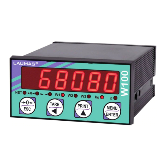
LED AND KEY FUNCTION Main function Secondary function * net weight (semi-automatic tare or preset tare) LED lit: input 1 closed zero (deviation from zero not more than ±0.25 divisions) LED lit: input 2 closed stability LED lit: input 3 closed unit of measure: kg LED lit: output 4 closed unit of measure: g... -
Page 13: Menu Map
MENU MAP Into menus changes are applied right after pressing the ENTER key (no further confirmation is required). SETPOINT … … … SYSTEM PARAMETERS ... -
Page 14: Instrument Commissioning
INSTRUMENT COMMISSIONING Upon switch-on, the display shows in sequence: - → (ONLY in case of approved program); - instrument model (e.g.: ); - followed by the software code (e.g.: ); - program type: (base); - followed by the software version (e.g.: ); - ... -
Page 15: Programming Of System Parameters
PROGRAMMING OF SYSTEM PARAMETERS From the weight display, press simultaneously keys MENU and ESC to access the parameter setting. MENU/ENTER: to enter a menu/confirm the data entry. ▲: to modify the displayed figure or menu item. ◄: to select a new figure or modify the displayed menu item. ESC: to cancel and return to the previous menu. -
Page 16: Maximum Capacity
MAXIMUM CAPACITY : Maximum displayable weight (from 0 to max full scale; default: 0). When the weight exceeds this value by 9 divisions, the display shows . To disable this function, set 0. TARE WEIGHT ZERO SETTING ... -
Page 17: Filter On The Weight
By confirming the message the flashing value of the weight currently on the system is displayed. In this phase all of the LEDs are off. Adjust the value on display by using the arrow keys if necessary. After confirming, the new set weight will appear with all the LEDs flashing. After an additional confirmation, the message ... -
Page 18: Anti Peak
The filter enables to stabilise a weight as long as its variations are smaller than the corresponding “response time”. It is necessary to set this filter according to the type of application and to the full scale value set. FILTER VALUE Response times Display and serial port refresh [ms]... -
Page 19: Automatic Zero Setting At Power-On
AUTOMATIC ZERO SETTING AT POWER-ON (from 0 to max 20% of full scale; default: 0): If at switch-on the weight value is lower than the value set in this parameter and does not exceed the value, the weight is reset. To disable this function, set 0. -
Page 20: Display Coefficient
DISPLAY COEFFICIENT By setting the coefficient the display is changed accordingly. If one of the inputs is set to mode (see section OUTPUTS AND INPUTS CONFIGURATION) when the input is closed the value will be displayed modified according to the ... -
Page 21: Outputs And Inputs Configuration
REAL CALIBRATION’S CHANGE FOR OTHER UNITS OF MEASURE Load a known quantity of product litres on the scale (equal to at least 50% of the maximum amount that you must weigh) and enter in the parameter , the product loaded value in litres. Also, if you set the parameter ... -
Page 22: Semi-Automatic Tare (Net/Gross)
- setpoint = 0 and switching = : relay switching occurs for a weight higher than or equal to 0, the relay will switch again for values below 0, taking hysteresis into account. - setpoint = 0 and switching = : relay switching occurs for a weight lower than or equal to 0, the relay will switch again for values above 0, taking hysteresis into account. -
Page 23: Preset Tare (Subtractive Tare Device)
Example: Put the box on the scale, the display shows the box weight; press TARE, the display shows the net weight to zero; introduce the product in the box, the display shows the product weight. This operation can be repeated several times. While the net weight is displayed, keep ▲... -
Page 24: Semi-Automatic Zero (Weight Zero-Setting For Small Variations)
SEMI-AUTOMATIC ZERO (WEIGHT ZERO-SETTING FOR SMALL VARIATIONS) By closing the SEMI-AUTOMATIC ZERO input, the weight is set to zero; alternatively, by pressing key for less than 3 seconds, the message is displayed for 3 seconds, by pressing ENTER the weight is set to zero. This function is only allowed if the weight is lower than the ... - Page 25 - : choice of a weight followed by the analog output: gross () or net (). If the net function is not active, the analog output varies according to gross weight. - : set the weight value for which you wish to obtain the minimum analog output value. Only set a value different from zero if you wish to limit the analog output range;...
-
Page 26: Serial Communication Setting
All analog outputs of the instrument are ACTIVE and SINGLE ENDED type, therefore they can be connected only to PASSIVE receiver devices. The minimum load allowed for voltage outputs is 10 kohm, the maximum load allowed for current outputs is 300 ohm. Voltage or current analog signal ACTIVE PASSIVE... - Page 27 - : weight reception mode (see section WEIGHT READING VIA SERIAL PORT). - : weight reception mode (see section WEIGHT READING VIA SERIAL PORT). - : transmission speed (2400, 4800, 9600, 19200, 38400, 115200; default: 9600). - : instrument address (from 1 to 99; default: 1). - : maximum transmission frequency (10 –...
-
Page 28: Rs232 Serial Communication
RS232 SERIAL COMMUNICATION INSTRUMENT RS232 TXD RS232 RXD DB9-F RS485 SERIAL COMMUNICATION INSTRUMENT INSTRUMENT INSTRUMENT max 500 m 24 VDC RS485 + RS485 + RS485 - RS485 - CONVLAU If the RS485 network exceeds 100 metres in length or baud-rate over 9600 are used, two terminating resistors are needed at the ends of the network. -
Page 29: Weight Reading Via Serial Port
Receiving instrument INSTRUMENT Connector Signal RS485: - W100 TERMINAL RS485: + RS485: SHIELD, GND If the RS485 network exceeds 100 metres in length or baud-rate is higher than 9600, two terminating resistors are needed at the ends of the network. Two 120 ohm resistors are to be connected, between the “+”... -
Page 30: Rs232 Connection
Receiving instrument TX RX INSTRUMENT Connector Signal RS232: TXD W100 TERMINAL RS232: RXD RS232: SHIELD, GND COMMUNICATION SETTING Into the SERIAL COMMUNICATION SETTING section (see receiving instrument manual), select the desired serial port and operation mode: WEIRIP () or WEIMOD (). -
Page 31: Weimod Mode
WEIMOD MODE Receiving instrument works as if the load cell is directly connected to the instrument. It’s therefore possible to perform calibrations and zero-settings on the receiving instrument. The used protocol is Modbus (the transmitting instrument works as "slave" and the receiving as "master"). Prior to set the ... -
Page 32: Test
TEST - Input Test: : ensure that for each open input is displayed, is displayed when the input is closed. - Output Test: : setting ensure that the corresponding output opens. Setting ensure that the corresponding output closes. -
Page 33: Setpoint Programming
SETPOINT PROGRAMMING From the weight display, press MENU to access the setpoint setting. MENU/ENTER: to enter a menu/confirm the data entry. ▲: to modify the displayed figure or menu item. ◄: to select a new figure or modify the displayed menu item. ESC: to cancel and return to the previous menu. -
Page 34: Alarms
ALARMS : the load cell is not connected or is incorrectly connected; the load cell signal exceeds 39 mV; the conversion electronics (AD converter) is malfunctioning; the load cell is a 4- wire and there are no jumpers between EX- and REF- and between EX+ and REF+. : communication problems between transmitter and receiver;... - Page 35 Serial protocol alarms: MODE The response to the Bit LSB 76543210 76543210 76543210 76543210 76543210 zero command is a On gross: xxxxxxx1 xxxx1xxx xxxxxx1x xxxxx1xx Status 'value not valid' error xxx1xxxx Register (error code 3) On net: MODBUS RTU xx1xxxxx...
-
Page 36: Printing Examples
PRINTING EXAMPLES If the printer has been set (see section SERIAL COMMUNICATION SETTINGS), from the weight display press the PRINT key for less than 3 seconds: BASIC PRINTOUT ----------------------- W100 BASE Addr:01 DATE: 12/09/11 14:48:12 GROSS 878 kg 589 kg... -
Page 37: Reserved For The Installer
RESERVED FOR THE INSTALLER MENU LOCKING Through this procedure, it’s possible to block the access to any menu on the instrument. Select the menu that you wish to lock: press ESC and ◄ simultaneously for 3 seconds, the display shows ... -
Page 38: Keypad Or Display Locking
PROGRAM SELECTION: confirm and use the arrow keys to select the desired program: : basic program, setpoint management only. : to be used when the loaded weighing system correspond to not loaded cells and vice versa (product increases while weight on load cells actually decreases). : weight remote display program with setpoint. -
Page 39: Declaration Of Conformity - Eu
CERTIFICAZIONE DEL SISTEMA DI GARANZIA DELLA QUALITÀ DELLA PRODUZIONE email: laumas@laumas.it web: http://www.laumas.com LAUMAS Elettronica S.r.l. Tel. (+39) 0521 683124 - Fax (+39) 0521 681091 Fabbricante metrico Prot. N. 7340 Parma - R.E.A. PR N. 169833 - Reg. Imprese Via 1° Maggio 6 – 43022 Montechiarugolo (PR) Italy PR N.19393 - Registro Nazionale Pile N°...
Need help?
Do you have a question about the W100 and is the answer not in the manual?
Questions and answers
can w100 work on all areas aggregate, cement , addictive and water
The LAUMAS W100 can control batching for aggregate materials, cement, additives, and water by weight or pulses. However, the document does not specify compatibility with all types of these materials. It ensures that batching can start independently for aggregates while other scales are still in process, but no details are provided about material-specific limitations.
This answer is automatically generated