
Related Manuals for AC Air Technology AC TRACKTECH T1X4

Summary of Contents for AC Air Technology AC TRACKTECH T1X4
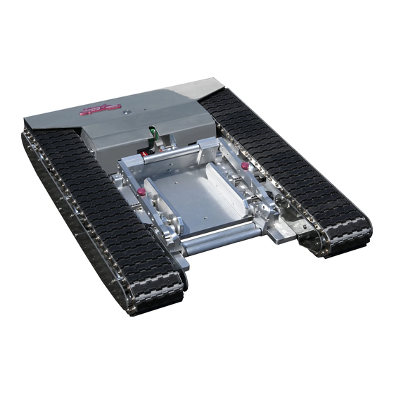
- Page 1 MODEL: AC TRACKTECH T1X4 Instruction Manual 95582 Rev. A World’s First Portable, Remote-Control Aircraft Tugs...
-
Page 2: Table Of Contents
Contents 1. Components 1-1. Components in the Box 1-2. Tug Components 1-3. Spare Parts Bag 1-4. Track Tools 1-5. On-Board Parts Box 2. Start-Up Guide 2-1. Radio Operation 2-2. Operating the Tug 2-3. Adjusting the Wheel Cradle 2-4. Adjusting Tire Guide Spacers 2-5. -
Page 3: Components
1. Components 1-1. Components in the Box Booster Plate Foam Stand (Part of tug shipping foam) Radio Transmitter Battery Tray Radio Charger Tug Charger Owners Manual Spare Parts Bag... -
Page 4: Tug Components
1. Components 1-2. Tug Components Rear Cradle Gate Wheel Cradle Ramp Power Switch Tug Charging Port Left Rail-Track Assembly Cradle Release Lever Electronics Cover Electronics Mainplate Assembly Right Rail-Track Assembly Cradle Mainplate Assembly... -
Page 5: Spare Parts Bag
1. Components 1-3. Spare Parts Bag • Spare Track Parts Rotoclips Pins • Track Install Tools • Fuses 4A mp Replacement Light Fuse Track Pin Tools 10 Amp Replacement Circuit Board Fuse... -
Page 6: Track Tools
1. Components 1-4. Track Tools The Track Tools are used to assist in the installation of new tracks. This section is intended to show how the tools are used only. Note: A detailed instruction guide is provided when purchasing new tracks. Refer to that instruction guide when installing new tracks. - Page 7 The Track Pin Tools are used to assist in the installation of new tracks Insert the Track Pin Tools on the inside and outside adjacent pins to the missing pin hole. Note: You will need to hold these in place by hand. Track Pin Tool Adjacent Pin Missing Pin Hole...
-
Page 8: On-Board Parts Box
1. Components 1-5. On-Board Parts Box The On-Board Parts Box contains spare track links, clips, and tools to quickly replace or repair tracks. It also includes cradle shims and mounting screws to lift the wheel cradle ramp away from the ground. When the ground is very uneven the wheel cradle ramp may hit the ground preventing the aircraft from loading.These components are located on-board the tug, underneath the electronics cover. -
Page 9: Start-Up Guide
2. Start Up Guide 2-1. Radio Operation Power Indicator Control Stick 3 Speed Toggle Light Switch Latch Switch Charging I ndicator ON/OFF Switch Charging Jack Lanyard Anchor Note: The 3 Speed Toggle ranges from fast, moderate, and slow. When operating the tug at slow speeds it may be neccessary to switch to the moderate or fast speed position on the toggle when turning at 90 degrees. - Page 10 2. Start Up Guide 2. To drive the tug, move the control stick in the desired direction. Forward Left Right Reverse Reverse Right Left Forward Warning: The joystick on the remote control is very sensitive and will cause the tug to move if it is moved accidentally. When not using the remote it is recommended that the power switch is turned OFF.
-
Page 11: Operating The Tug
2. Start Up Guide 2-2. Operating the Tug 1. Before turning on the tug, make sure that the tracks and bottom of the tug are free from obstruction. 2. Turn the tug on using the ON/OFF switch. There will be a short series of beeps and then the ON/OFF switch will illuminate red to show the tug is on. - Page 12 5. When towing your airplane ALWAYS be cautious of the steering angle limitations of your aircraft. Do not oversteer your aircraft with the tug. This can cause damage to your gear. 6. After lifting the tug off of the ground for any reason or taking it in and out of your aircraft, you must check to make sure the sprockets are correctly seated on the tracks.
- Page 13 2. Start Up Guide 2-3. Adjusting Wheel Cradle to Your Tire 1. When towing a non-fairing aircraft make sure the front and back cradle gates are adjusted in the fully extended position. For aircraft with fairings adjust the cradle gates to the lowest setting.
- Page 14 3. To adjust the back gate loosen the 4 fl at head screws on the back of the gate. Then slide the right and left sliders to the desired position. Tighten all 4 of the fl at head screws. Note: It may be easier to remove these screws with the link locking pins removed. Right and Left Sliders Flat Head Screws 4.
- Page 15 5. Place wheel chocks behind the rear tires of plane to ensure the plane does not roll back. 6. Drive tug under the wheel of the plane until the wheel cradle locks in the upright position. Make sure the wheel is touching the back gate as shown. Wheel touching here...
- Page 16 5. Remove the adjustment pins and push the front side of cradle until it is touching the tire and re-install the pins. If the pins cannot be installed while the front side is touching the tire, move the front side of cradle away from the tire until the pin can be inserted into the next closest hole.
-
Page 17: Adjusting Tire Guide Spacers
2. Start Up Guide 2-4. Adjusting the Tire Guide Spacers Adjustment Pin Tire Guide Spacer 1. If the tire guide spacers are in the widest position and your tire does not fi t or it is too close of a fi t, remove the tire guide spacers and adjustment pins. Widest Postion... - Page 18 2. Adjust the tire guide spacers by removing the adjustment pin and sliding the spacers towards eachother. Ideally the tire guide spacers should move the same distance on each side to keep the tire centered in the cradle. The distance between the tire guide spacers should equal the width of your tire plus one inch maximum.
-
Page 19: Adjusting Track Tension
2. Start Up Guide 2-5. Adjusting the Track Tension Track tension might need to be adjusted after several hours of use. Follow the instructions below for each track. 1. Remove 6 track cover screws and remove the outside plastic track cover. Track Cover Screws Plastic Track Cover 2. - Page 20 3. Push the rail end forward using a small pry bar to tighten up the track. There should be about a 1/2” of play at the center of the track. Push Rail 1/2” Up and Down Play at Center of Track End Forward 4.
- Page 21 If the issue persists call or email AC Air Technology tech sup- port for further assistance.
- Page 22 2. Start Up Guide 2-7. Unloading the Airplane Wheel Off of the Tug 1. Turn the tug power ON and the radio power ON if not already on. 2. Push the tug slightly forward so the airplane tire puts pressure on the back gate of the cradle.
-
Page 23: Lifting The Wheel Cradle Ramp
2. Start Up Guide 2-8. Lifting the Wheel Cradle Ramp The cradle shims are used to lift the wheel cradle ramp away from the ground. When traversing on very uneven terrain the wheel cradle ramp may hit the ground and prevent the aircraft from loading onto the tug. 1. - Page 24 2. Start Up Guide 2. Install the cradle shims onto the Cradle Front Adjusting Arms. Apply thread- locker to the screws to prevent them from vibrating off . Note the orientation of the shim with respect to the cradle front adjusting arms. There should be a small gap between the cradle front adjusting arm and cradle shim as shown below.
-
Page 25: Charging The Tug
2. Start Up Guide 2-9. Charging the Tug 1. Before charging your tug, be sure the radio and tug are both turned OFF. Charging Jack Charging Indicator Light 2. The charging indicator light on the charger should light up red once the charger is connected properly. -
Page 26: Charging The Transmitter
2. Start Up Guide 2-10. Charging the Transmitter WARNING: Only use the supplied charger to charge the transmitter when using the supplied batteries or the following: - 1200mAh Ni-MH or Ni-Cd ‘AA’ Rechargeable Batteries The use of the transmitter charger with alkaline batteries installed can damage the transmitter. -
Page 27: Replacing Transmitter Batteries
2. Start Up Guide 2-11. Replacing the Transmitter Batteries 1. Remove 4 cover screws from back of transmitter case. 2. Replace old battery pack with new battery pack. Note: A battery tray is provided with the tug. It can be used with standard AA rechargable batteries. - Page 28 4A. Replace the batteries by purchasing a new shrink wrapped Note: A shrink wrapped battery pack can battery pack from AC Air Technology be purchused from AC Air Techology to or installing the supplied battery tray replace the installed battery tray. To use a and purchasing 6 rechargable ‘AA’...
-
Page 29: Disassemble / Reassemble Tug
3. Disassemble / Reassemble Tug Disassemble Tug 1. With the wheel cradle in (up) locked position, lift the front-end of the tug and slide the provided foam stand underneath the tug. The foam stand has the following dimenisons, 19” x 11” x 2-1/4”. It is stored in the shipping box, foam packaging) (1) Lift from here Foam stand should sit centered on the tug, aligned to the back of the electronics main-... - Page 30 3. With one hand, apply pressure upward on the bottom, center, of the rail-track assembly to relieve pressure off the rail-track assembly lock pin. Turn the quarter-turn fasteners (90 degrees), 2 per side. The quarter-turn fasteners should be easy to turn once the pressure is off...
- Page 31 5. Manually unlatch the wheel cradle and place it in (down) loading position. 6. With the cover open, hold the electronics mainplate assembly by the handles. Slightly tilt the assembly forward and slide it to the right until the connection tabs are in the unlocked position.
- Page 32 6. Lift the electronics mainplate assembly straight up. Always use both handles when maneuvering the electronics mainplate assembly. Lift up Note: Weight per subassembly 25 lb 25 lb 25 lb 20 lb...
- Page 33 Reassemble Tug The foam stand has the 1. Place the cradle mainplate assembly on top of the foam stand. following dimenisons, 19” x 11” x 2-1/4”. It is stored in the shipping box, foam packaging) 2. Manually unlatch the wheel cradle and place it in (down) loading position. Foam stand Cradle mainplate assembly Wheel cradle in...
- Page 34 4. Slightly tilt the electronics mainplate assembly forward and slide it to the left until the connection tabs are in the locked position. Check the latch and cam for proper seating. (2) Slide left Keep cover open (1) Slightly tilt the electronics mainplate assembly forward Tabs in unlocked position...
- Page 35 5. Align the shaft teeth, rotate the motor by hand if the teeth are not engaging correctly. 6. Align the quarter-turn lock pin fasteners with its respective receptacle. 7. Apply pressure upwards on the bottom, center of the rail-track assembly and press the quarter-turn fastener down into the receptacle.
-
Page 36: Troubleshooting
The troubleshooting guide is divided into three sections: Tug, Remote Controller, Wheel Cradle. Refer to the images and descriptions below as they are mentioned throughout the text. Servo Speed Control Latch Mechanism Radio Receiver For technical support call or email AC Air Technology (855) 884-7222 info@acairtechnology.com... -
Page 40: Warranty
In no event shall the liability of AC Air Technology exceed the individual price of the product on which liability is asserted. AC Air Technology has no control of the set up, ap- plication, use, modifi cation, or misuse of this product, thus no liability shall be assumed or ac- cepted for any resulting damage or injury.
Need help?
Do you have a question about the AC TRACKTECH T1X4 and is the answer not in the manual?
Questions and answers