Table of Contents
Advertisement
Quick Links
Advertisement
Table of Contents

Subscribe to Our Youtube Channel
Related Manuals for Howe Rapid Freeze 1000-RLE-CO2DX


Summary of Contents for Howe Rapid Freeze 1000-RLE-CO2DX
- Page 1 Ice Flaker Rapid Freeze ® Installation & Service Manual For Use with Parallel Compressor Rack System 1000-RLE-CO 2000-RLE-CO Phone: 1-773-235-0200 Howe Corporation Fax: 1-773-235-0269 1650 North Elston Avenue Website: www.howecorp.com Chicago, IL 60642-1585 Email: howeinfo@howecorp.com...
-
Page 2: Table Of Contents
ENGINEERING GUIDELINES .........................3 Location Requirements ................................3 Electrical Requirements ................................3 Water Supply Requirements ..............................3 Drain Water Piping Requirements ............................4 Refrigeration Requirements ..............................5 Piping Table..................................... 7 Refrigerant Pipework ................................7 Refrigerant Pipework Insulation Requirements ........................7 FIELD INSTALLATION ..........................8 Safety Information and Guidelines ............................ -
Page 3: Engineering Guidelines
The cold water supply pressure must be within If installing the Ice Flaker with a Howe Ice Bin, a 20 PSIG (140 kPa) to 60 PSIG (410 kPa) range. ensure that the bin is adequately secured to... -
Page 4: Drain Water Piping Requirements
Generally, filtration of cold supply water is recommended. Howe offers a complete line of replaceable core cartridge filter treatment systems designed to improve ice quality and extend the life of the Ice Flaker. -
Page 5: Refrigeration Requirements
Racks equipped with gas defrost are not No suction pressure regulating valve of any type recommended for use with Howe Ice Flakers. should be assigned to the Ice Flaker at the Rack or suction line branch. If a liquid line solenoid is... - Page 6 Figure 1...
-
Page 7: Piping Table
Field refrigerant pipework should be insulated page. with closed cell flexible elastomeric foam thermal insulation intended for cold Howe recommends the use of hard drawn ACR applications. type L tubing with refrigeration grade wrought copper long radius elbows and fittings only. No Liquid lines should be covered with 1/2”... -
Page 8: Field Installation
Field Installation Piping Safety Information and Guidelines The Ice Flaker has been thoroughly cleaned and Only qualified service technicians should dehydrated at the factory. However, foreign attempt to install, service, or maintain the Ice matter may enter the system by way of the Flaker. -
Page 9: Field Wiring
Evacuation Field Wiring Do not use the refrigeration compressor to All field wiring must be in compliance with local evacuate the system. Do not start the and national codes. Use only copper compressor while it is in a vacuum. conductors of the appropriate size. A good, deep vacuum pump should be 1. -
Page 10: Installation Checklist
Installation Checklist 1. Has the ambient temperature been verified between 50°F – 100°F (10°C-38°C)? (see Location Requirements p. 3) 2. Has the incoming water temperature been verified between 45°F – 90°F (7°C – 32°C)? (see Water Supply Requirements p. 3) 3. -
Page 11: Start Up And Operation
Start Up and Operation Water Operation 1. Water Inlet Connection 6. Sump Connections 2. Float Valve 7. Stop Valve 3. Water Pump 8. Condensate Drain Outlet 4. Water Regulating Valve 9. Sump Drain Outlet 5. Water Distribution Pan & Side Spout... - Page 12 Water Inlet The supply water feed for the Ice Flaker must be connected here. A shut-off valve should be field installed before this connection. The Ice Flaker requires a minimum water pressure of 20 PSIG (1.4 bar) and a maximum of 60 PSIG (4.1 bar).
- Page 13 Water Distribution Pan Water Regulating Valve The Water Distribution Pan circulates the water Adjust the water level in the Water Distribution fed from the Water Pump down the walls of the Pan by opening or closing the Water Regulating Evaporator. Valve located directly above the Water Sump.
-
Page 14: Refrigerant Operation
Refrigerant Operation *Piping insulation not shown 1. Solenoid Valve 4. Pressure Transducer 2. Electronic Expansion Valve (EEV) 5. Evaporator Pressure Regulator (EEPR) 3. Evaporator 6. Pressure Relief Valves... - Page 15 Field Capacity Check Solenoid Valve The Ice Flaker is a continuous production The Solenoid Valve controls the flow of liquid machine and makes ice at a steady rate once refrigerant to the Evaporator. stabilized. The Solenoid Valve should energize A Capacity Check confirms the Ice Flaker and immediately upon starting the Ice Flaker.
-
Page 16: Electrical Operation
Electrical Operation 1. Level Control Relay (LC1) 5. Power Switch 2. Motor Relay (R1) 6. Ice Flaker Run Indicator Light 3. Control Module (CM) 7. Motor Overload Indicator Light 4. Transformer (T1) 1. Term 1: 24V Input Power 7. Term 7: Solenoid Valve Contact 2. - Page 17 Level Control Relay (LC1) This relay processes the signal from the Photo Normal Operation Normal Operation begins when the Control Eyes. It shuts the Ice Flaker off when the Ice Bin Module senses voltage at the Control Signal is full to prevent damage caused by ice backing (Term 3).
- Page 18 Motor Overload Setting Overload Condition The proper adjustment of Motor Overload An Overload Condition begins when the Setting will protect the Ice Flaker and help avoid Overload Sensing Coil reads amperage from the nuisance service calls. motor lead passing through it that is higher than the Motor Overload Setting.
- Page 19 Photo Eyes (Level Control) Emitter Receiver Part# E20T104 Part# E20T105 Two Pins ( Blue & Brown ) Three Pins ( Blue, Black, & Brown ) One LED ( Green) Two LEDs ( Green & Amber )
- Page 20 Bin the Photo Eyes will be shipped loose and need to be properly mounted by the installing The Emitter has a green LED, which is contractor. Please contact Howe for further illuminated whenever the Ice Flaker has power. information. The Receiver has two LEDs. The green LED is...
-
Page 21: Electronic Valve Settings
Electronic Valve Settings From this menu the setpoints can be changed to the factory settings. To exit the menu and If the controllers need to be reset at any time, save settings, scroll the knob until ‘ESC’ appears the factory settings for each controller are listed and press the select knob. - Page 22 Kelvin II (EEV) Setpoints Displayed Description Factory Setpoints Menu Item 1000 2000 Escape and Save Settings SHSP Superheat Setpoint rEFr Refrigerant R744 R744 d_On Delay On doFF Delay Off d_St Delay Step Position Open of Valve b_St Bleed Step Position of Valve % 0.0% 0.0% b_dL...
-
Page 23: Mechanical Operation
Mechanical Operation 1. Ice Deflector 4. Speed Reducer 2. Ice Blade 5. Drive Motor 3. Squeegee... - Page 24 The 2000-RLE and 3000-RLE also feature an Ice Ice Deflector Deflector Scraper. This plastic arm clears any The Ice Deflector prevents ice from dropping excess buildup of ice on the Ice Deflector as it into the water return trough. passes by the Ice Deflector Scraper. The Ice Deflector should never touch the Ice Deflector Scraper or the Bottom Casting.
- Page 25 The Auxiliary Ice Scrapers located at the top and Gear Motor (1000-RLE) The Gear Motor is a drive motor and speed bottom (2000-RLE bottom only) of the Ice Blade reducer combined in one single unit. remove any ice forming in those areas. The clearance of the Auxiliary Ice Scraper should be the same or slightly greater than the Ice Blade.
- Page 26 Ice Flaker. Drive Motors may provide a good deal of resistance when being removed. There are (2) Howe is proud to offer our Factory Rebuild threaded holes on the face of the Speed Program as an alternative to replacing parts Reducer in which the mounting screws can be such as the Sleeve Bearings in the field.
- Page 27 Start-Up Checklist 1. Is the operating water level in the Water Sump correct? (see Float Valve p.12) 2. Is the operating water level in the Water Distribution Pan correct? (see Water Distribution Pan p.12) 3. Is the Stop Valve on Sump Drain connection closed? (see Stop Valve p.12) 4.
-
Page 28: Preventative Maintenance Schedule
Maintenance Preventative Maintenance Schedule Page Every 3 Every 6 Every 12 Number Months Months Months Lubricate Sleeve Bearings • Ensure Float Valve is unclogged and • flowing freely Verify correct Sequence of • Operation of Photo Eye sensors Clean and Sanitize Ice Flaker •... -
Page 29: Cleaning Procedure
Cleaning Procedure To keep the evaporator in peak performance, the Ice Flaker should be cleaned every 6 months or more often if water conditions dictate. Only use cleaning solutions that are labeled as “Nickel-Safe”. 4. Close water supply at shut-off valve. 1. -
Page 30: Sanitizing Procedure
Sanitizing Procedure 1. Mix 16 oz. of household bleach with 2 gallons of warm water (90°F – 115°F). 2. Pour solution into the Water Sump to the normal operating level, then re- circulated the sanitizing solution for approximately 20 minutes by turning on Drive Motor and Water Pump. -
Page 31: Lubrication
Lubrication Gear Motor Lubrication Typically, only one squirt of the grease gun is The Gear Motor is permanently lubricated and required or until you feel resistance on the does not normally require re-lubrication. pump. Speed Reducer Lubrication Use caution to ensure the bearings is not over- All speed reducers are to be filled with Mobil greased. -
Page 32: Water Filtration
cause added wear on parts and can clog valves Water Filtration and impede flow. The purpose of water filtration is to keep the Ice Flaker clean and operating efficiently. The value to the user is reduced operating cost due to less maintenance, improved performance and a greater return on investment as result of extended asset life. - Page 33 Howe Water Filters Howe offers a complete line of water treatment systems designed to extend the life and performance of the Ice Flaker. Howe Water Filters inhibit the formation of scale and provides additional corrosion protection. They remove 95% of all dirt, rust, and sediment larger than 5 microns.
-
Page 34: Troubleshooting
Troubleshooting (Note: All wire colors are subject to change) Problem Possible Cause Possible Solution 1. Unplugged or defective Photo Eye(s). 1. Ensure Molex plugs are properly and securely connected. Place a wire jumper between terminals #10 (blue) and #11(black) at the Level Control Relay (LC1). If Ice Flaker starts, Photo Eyes may be defective and need to be replaced. - Page 35 2. Adjust Ice Blade clearance to proper setting. 1. Ambient Temperature is too low. 1. If ambient temperature is below 50°F, relocate Ice Flaker to a warmer area. Ice accumulates on the ribs of Contact Howe about Low Ambient Kit. Bottom Casting...
- Page 36 4. Check that all drains are flowing freely and pitched away from Ice Bin. 5. Ice turnover is low and Ice Bin inventory 5. Use or discard ice within a reasonable time of producing it. Contact Howe about has become stale and clumped by lengthy Energy Saver Ice Production Management System.
-
Page 37: Appendix
Appendix Cut View – 1000-RLE... - Page 38 Cut View – 2000-RLE...
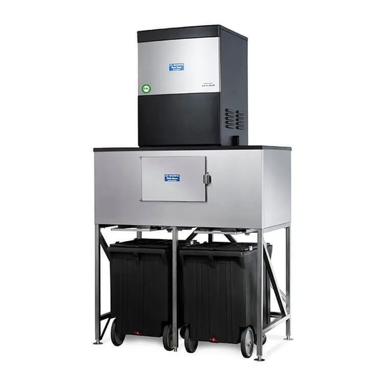
- Page 39 Assembly Drawing – 1000-RLE Ice Flaker & CP750 Mobile Express Ice Bin...
- Page 40 Assembly Drawing – 2000-RLE Ice Flaker & CP1500 Mobile Express Ice Bin...
- Page 41 Wiring Diagram – Ice Flaker Main Control Panel...
- Page 42 Wiring Diagram – CO2 EEV/EEPR Control Panel...
- Page 43 Installation & Service Manual For Use with Parallel Compressor Rack (CO2DX-RLE) Revision Date: Mar-20...
Need help?
Do you have a question about the Rapid Freeze 1000-RLE-CO2DX and is the answer not in the manual?
Questions and answers