
Related Manuals for Njoy ACUP-SN000MP-AZ01B


Summary of Contents for Njoy ACUP-SN000MP-AZ01B
- Page 1 SNMP Card WP ACUP-SN000MP-AZ01B User manual 111.0 Before using this product, carefully read all product documentation and retain it for future reference.
-
Page 2: Table Of Contents
4.1.2 Basic information ....................10 4.2 UPS setting ......................... 11 4.2.1 Parameters setting ..................... 11 4.3 Control ......................... 13 nJoy UPS models that are compatible with this product: 4.3.1 Real-time control ....................13 4.4 System configuration ....................13 Aten Pro Series 1K / 2K / 3K 4.4.1 Web user ...................... -
Page 3: Product Overview
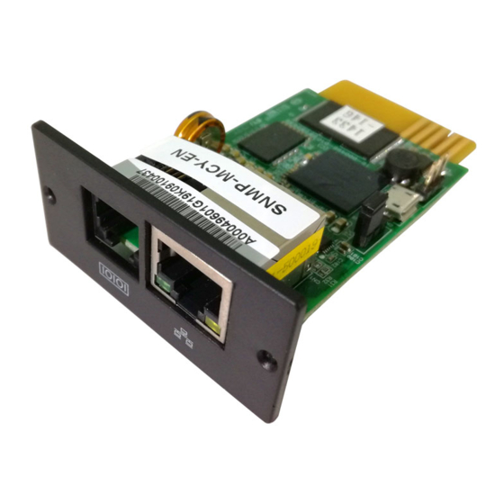
Ethernet port status LEDs: Product overview 100M LED (Green) Port is operating at 100Mbit/s Current web bandwidth is 10Mbit/s 2.1 Features Link status LED (Yellow) Flash Link Active • Open monitor via Web Browser. Card is not connected to the network •... -
Page 4: Configuration
Step 3: Plug Ethernet cable to the Ethernet port (RJ-45) on the SNMP web manager. Step 4: Use one more Ethernet cable. Connect one end to the sensor port on the SNMP web manager and the other end to the optional environ- mental monitoring device. -
Page 5: Snmp Web Pro Gui
SNMP web pro GUI SNMP web pro GUI includes function menu, login section and main screen. Refer to Chart 3-1: Chart 2-6 b 2. Installed ViewPower Pro software to monitor SNMP web pro. Refer to Chart 2-7. Please check ViewPower Pro User Manual for detailed monitoring. Chart 3-1 A. -
Page 6: Function Menu
4.2 UPS setting Function Menu 4.2.1 Parameters setting Some UPS functions can be set and changed via software. Parameter setting 4.1 Information includes backup time setting for programmable outlet (P1), battery number setting, voltage and frequency range setting for bypass mode and voltage 4.1.1 Status range setting for ECO mode. -
Page 7: Control
• Auto reboot: If enabled, UPS will auto recover when AC is recovering. Vice 4.3 Control versa. 4.3.1 Real-time control • Bypass when UPS is off: If enabled, AC will directly provide power to con- Select Control >> Real-time control. Refer to Chart 4-5. nected devices when UPS is off. -
Page 8: E-Mail
1. Enter SMTP server, security type (supported encryption from SMTP serv- er), SMTP port, sender’s E-mail address, user name and password. Click checkbox of “Need Auth” for password verify. 2. Enter correct e-mail accounts in Receive list. Then, click “Apply” to add into receivers list. -
Page 9: Wake On Lan
4.4.5 Shutdown It is to remotely shut down specific PCs with Shutdown Wizard. This function is only available to integrate with Shutdown Wizard. Please also check user manual of Shutdown Wizard for the details. Select System Configuration >> Shutdown. Refer to Chart 4-10. Chart 4-8 b 4.4.4 Wake on LAN It’s to remotely wake on specific PCs in LAN when these PCs are supported... -
Page 10: Scheduled
• Shutdown the PC while battery mode: When selected, integrated with 4.4.7 Scheduled Shutdown Wizard, local PC will shut down while UPS works on battery Select System Configuration >> Scheduled. Refer to Chart 4-12. mode. • Time needed for shutting down the PC: Enter the delay time to shut down the operating system. -
Page 11: System Time
4.4.8 System time Select System Configuration >> System time. Refer to Chart 4-13. Chart 4-14 a Chart 4-13 • Automatic time correction interval • Time server: The SNTP server IP address or domain name. • Time Zone (Relative to GMT): It’s measured to relative to GMT. •... -
Page 12: Log
• SNMP server configuration: You may change SNMP port and trap port. You also can add SNMPV3 users by clicking “Add” button. It will pop up a screen to set up user setting such as security level and permission level. Refer to below chart. -
Page 13: Help
4.6 Help 4.6.1 Serial Port Debug It’s to test communication condition between SNMP card and device. Select Log >> Event log. Refer to Chart 4-17. Disposal of Old Electrical & Electronic Equipment (Applicable in the European Union and other European countries with separate collection systems) This symbol on the product or on its packaging indicates that this product shall not be treated as household waste. - Page 14 Memo Memo...
Need help?
Do you have a question about the ACUP-SN000MP-AZ01B and is the answer not in the manual?
Questions and answers