Advertisement
Many Arroyo Instruments laser drivers feature an analog modulation input (typically 0-10V, Paks use a
lower voltage). This input is typically driven using a function generator. All well and good if you have a
function generator available. However, in some systems, the only signal available is a fixed trigger signal,
often 5V. This document explores how to use that fixed voltage signal with the modulation input to
achieve set point control.
Modulating Range and Output Current Range Defined
Modulation range refers to the difference between the maximum and minimum modulation current. For
example, if modulating between 2A and 6A, the modulation range would be 4A.
The output current range is the modulation range plus the Io Setpoint... the set point and the
modulation input sum together to form the output drive current. Note that when the source voltage is
off (0V), the diode will be driven by the amount of current as set with Io Setpoint.
Defining the Output Current Range
The first step is to determine the modulation voltage required to achieve the target output current. For
the following examples, we'll assume a +5V trigger signal is what's available, and that we are working
with a 4308 LaserSource, which has an 8A output and a 0-10V modulation input.
Your modulation range will be limited by your trigger voltage divided by 10V and multiplied by the range
of the instrument:
�������������� �������������������� ���������� = (
For a 4308 with a 5V source, this equates into 4 Amps. If you need to achieve a higher maximum
current, adjust the Io Setpoint up as needed. If in the trigger off state operating the diode at a non-zero
current is not acceptable, you will need a higher trigger voltage which is outside the scope of this
document.
AN-019 - Modulating Output with a Fixed Voltage
APPLICATION NOTE AN-019
Modulating Output with a Fixed
Voltage
February 19, 2020, Rev B
������������ ��
) ∗ �������������������� ����������
10��
Page 1
Advertisement
Table of Contents

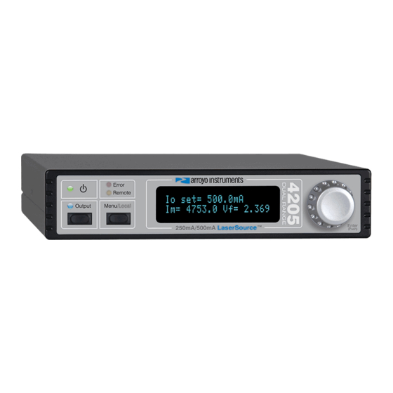
Summary of Contents for Arroyo Instruments 4205
- Page 1 Voltage February 19, 2020, Rev B Many Arroyo Instruments laser drivers feature an analog modulation input (typically 0-10V, Paks use a lower voltage). This input is typically driven using a function generator. All well and good if you have a function generator available.
- Page 2 Modulating at Half Range of the Driver Let’s assume your laser requires 5A operating current. With 5V trigger input, your maximum modulation range is limited to 4A. Therefore, to achieve a maximum of 5A, connect your trigger source directly to the modulation input BNC and change the Io Setpoint to 1000mA: your output current range would be between 1A and 5A.
- Page 3 at 5V, your voltage source will need to drive up to 12.5mA. Most sources should be able to deliver 12.5m, but might be something to confirm. One Resistor Method Alternatively, you could omit R2 altogether and use R3 as the fixed lower resistor. In this design, wire R1 as series resistor to the modulation input, as shown in the diagram below: Modulation Input BNC INPUT +...


Need help?
Do you have a question about the 4205 and is the answer not in the manual?
Questions and answers